

Ratchet wrench apparatus
a ratchet wrench and wrench technology, applied in the field of ratchet wrench apparatus, can solve the problems that prior art arrangements of record are not suitable for use with this type of ratchet wrench, and achieve the effects of convenient use, quick and convenient use, and low cos
- Summary
- Abstract
- Description
- Claims
- Application Information
AI Technical Summary
Benefits of technology
Problems solved by technology
Method used
Image

Examples
third embodiment
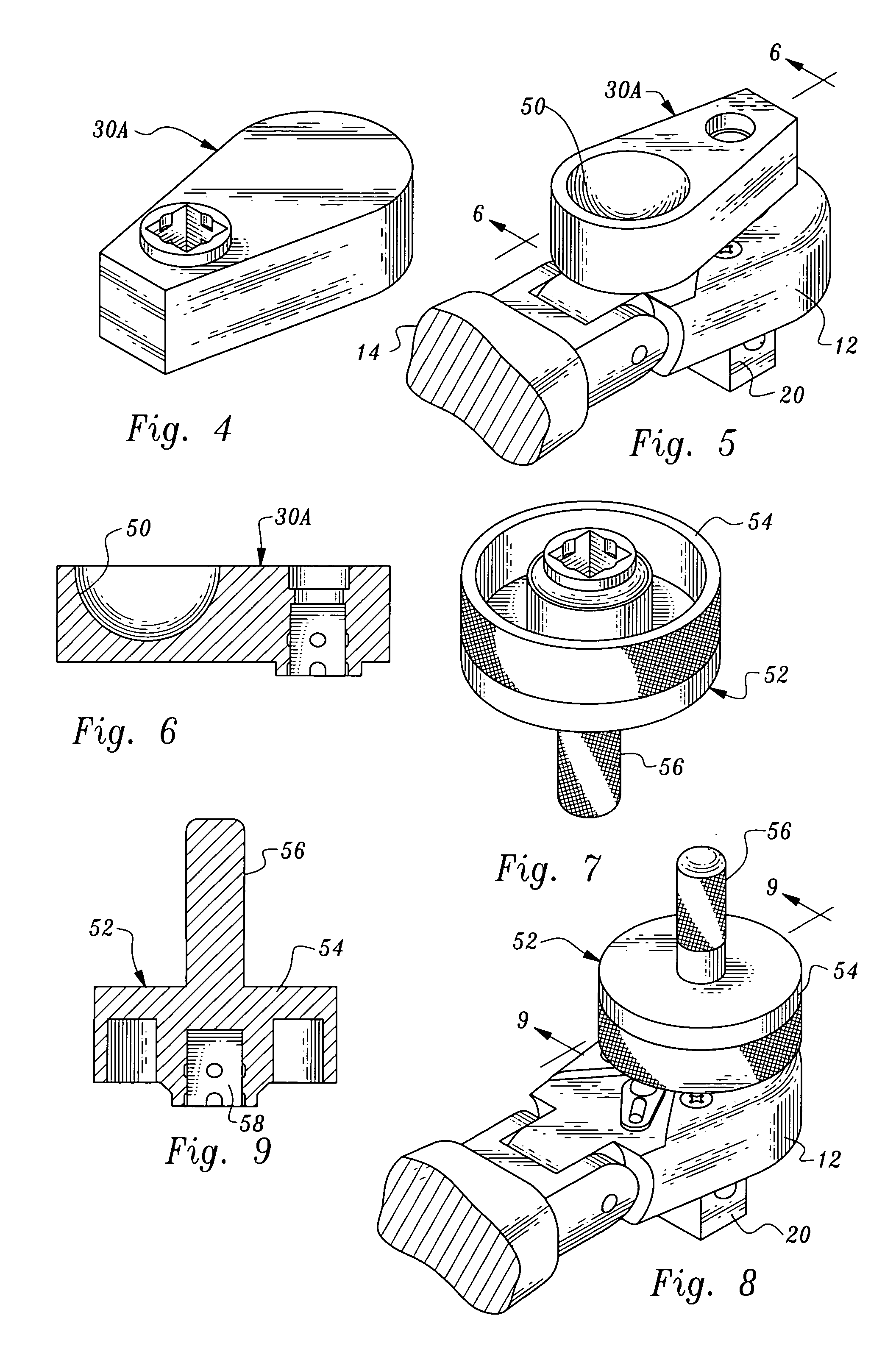
[0034]FIGS. 7, 8, 9 and 12 disclose manually engageable extension member, identified by reference numeral 52. This embodiment is in the form of a knob having two manually engageable knob portions 54, 56. Each of the knob portions has a cylindrically-shaped outer peripheral surface, at least a portion of which is knurled, as shown. The diameter of knob portion 54 is considerably less than that of knob portion 54 and an individual can use either, as appropriate, to turn the manually engageable extension member 52 when attached to a ratchet wrench as shown in FIG. 12. The projection 18 is seated in a recess 58.
fourth embodiment
[0035]FIGS. 13 and 14 illustrate manually engageable extension member, identified by reference numeral 60. In this embodiment, a cylindrically-shaped wall 62 extends upwardly from the distal end 64 to define a hole in the form of recess 66.
fifth embodiment
[0036] the invention is shown in FIG. 15 and identified by reference numeral 70. In this arrangement a hole in the form of a throughbore 72 is located at distal end 74. A bearing 76 is located in throughbore 72 and a stem 78 of a manually engageable element 80 is rotatably mounted by the bearing. A recess 82 for receiving a user's finger is formed at the outer end of manually engageable element 80. During rotation of the manually engageable extension member by a user, the element 80 will rotate as well, so that the position thereof remains fixed relative to the user's finger.
[0037]FIG. 16 illustrates a sixth embodiment 90 similar to the embodiment of FIG. 15. In this instance, however, the manually engageable element comprises a graspable projection 92 extending upwardly from the throughbore 72.
PUM
 Abstract
Description
Claims
Application Information