Labeling method and device

a labeling and method technology, applied in the direction of labelling, mechanical control devices, lamination, etc., can solve the problems of affecting the accuracy of labeling, corresponding labeling errors, and higher speeds, and achieve precise labeling, precise maintenance of residual distance, and decisive enhancement of motion sequence accuracy

Active Publication Date: 2006-12-28
HERMA
View PDF15 Cites 22 Cited by
  • Summary
  • Abstract
  • Description
  • Claims
  • Application Information

AI Technical Summary

Benefits of technology

[0012] According to a second aspect of the invention, the stated object is achieved by first specifying a target position for the label and, during the label's motion, specifying a revised target position. By accurate specification of the residual distance, such an arrangement makes possible very precise labeling even if the label pitch varies slightly due to fluctuations in production, changes in relative humidity, etc.
[0013] Accurate maintenance of a residual distance during labeling has the following principal advantages:
[0014] a) The accuracy of the motion sequence is decisively enhanced.
[0015] b) The reproducibility of the motion sequence becomes very good.
[0022] According to a third aspect of the invention, this object is achieved by imparting a predetermined motion profile, having multiple phases, to the label's motion. A method of this kind makes possible very fast and precise labeling, changes in the labeling speed being possible without any changes in labeling precision.
[0025] A very compact and also high-performance labeling device is obtained, according to a further aspect of the invention, by putting the motor and its power electronics in a metal housing which serves as a heat sink or cooling element. The need for additional electrical cabinets, etc. is in many cases thereby eliminated, and costs for the installation of and, if applicable, modifications to a labeling apparatus are consequently low. Cleaning is moreover facilitated, and it is possible to conform to higher electrical protection classes without increased outlay, making it possible to use such labeling devices in refineries and other explosion-hazard facilities.

Problems solved by technology

Such methods yield entirely acceptable results, but problems occur at higher speeds, principally for the following reasons:
These forces, whose occurrence is governed by chance, can accelerate or decelerate the label strip, which can lead to corresponding labeling errors.
During the motion of the label strip / carrier strip, the latter can expand or contract similarly to a rubber band, particularly at the beginning of a transport motion; this “rubber band effect” can likewise negatively affect labeling accuracy and limits the labeling speed, since such effects increase with increasing speed.
This is because higher speeds result in correspondingly higher accelerations, and thus in greater forces on the label strip / carrier strip.

Method used


Image

  • Labeling method and device
  • Labeling method and device
  • Labeling method and device

Examples


Embodiment Construction

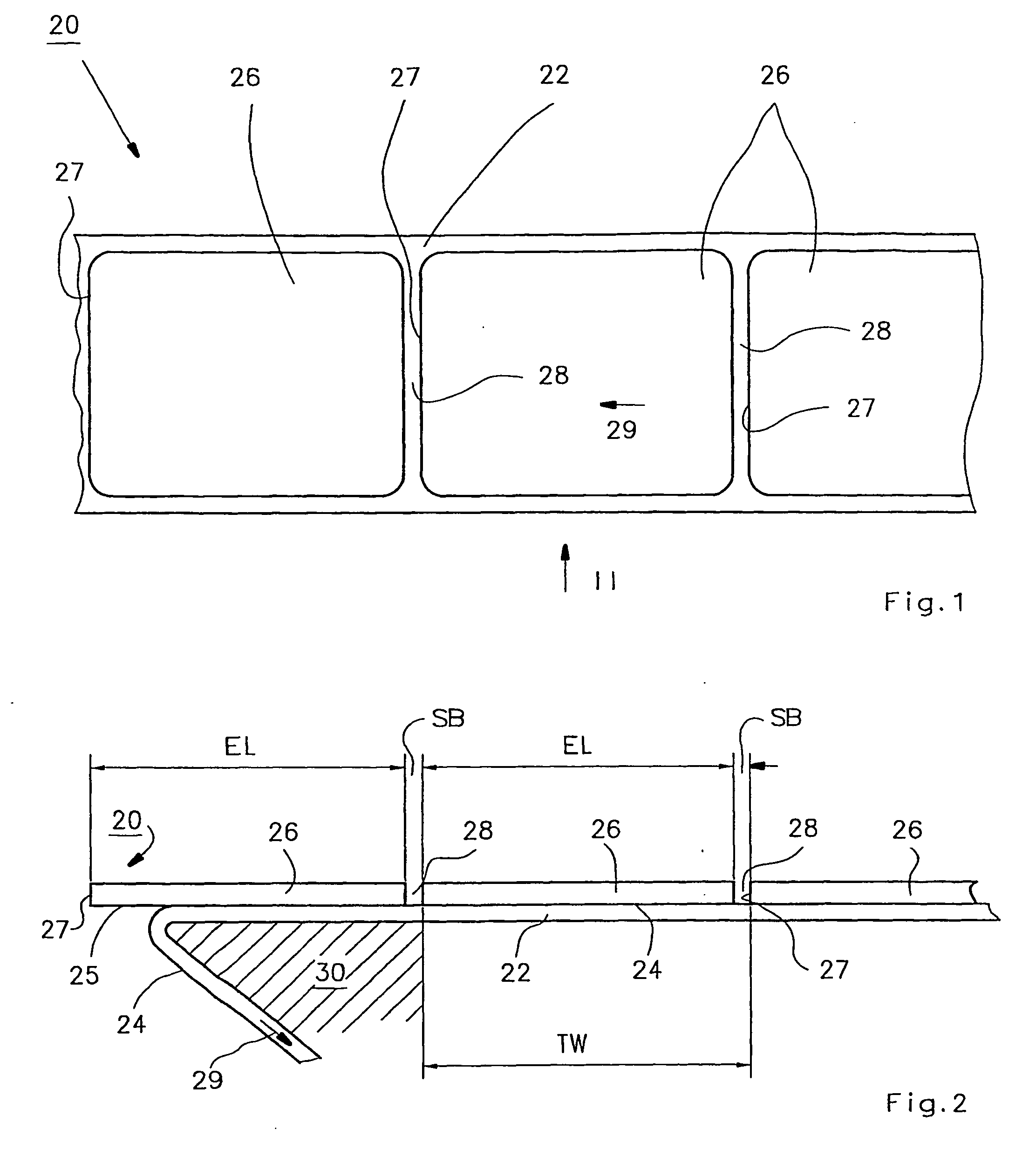
[0047]FIG. 1 is a plan view of a label strip 20, and FIG. 2 shows that strip in a side view. In the side view, the dimensions in the vertical direction are depicted in extremely exaggerated fashion to allow better comprehension of the invention.

[0048] Label strip 20 has, at the bottom in FIG. 2, a carrier strip 22, usually made of paper, that is provided on its upper side in FIG. 2 with a release layer 24, usually made of silicone. Self-adhesive labels 26 are adhesively bonded onto layer 24 by means of a contact adhesive layer 25. These labels have a label length EL that can be between a few millimeters and hundreds of millimeters. It is obvious that the labeling performance can be higher with short labels than with long labels. The direction of motion of label strip 20 is labeled 29, and the label edges that are toward the front in the direction of motion are labeled 27. Because label strip 20 and carrier strip 22 are identical except for the presence or absence of labels 26, the ...


PUM

PropertyMeasurementUnit
residual distanceaaaaaaaaaa
widthaaaaaaaaaa
widthaaaaaaaaaa

Abstract

In a method for labeling, a label strip (20) is moved by means of an electric motor (80). Arranged on this label strip are labels (26) of predetermined length (EL) with uniform interstices (SB). The motor has associated with it a position controller (218), also a sensor (44) for sensing a predetermined position of a label (26) when the latter is moved on the label strip (20) relative to the sensor (44). The method has the following steps: in accordance with a stored profile, the label strip (20) is set in motion beginning from a start position (A), a first target position (Z) of the label strip being specified to the position controller (218); during the motion of the label strip (20), a predetermined position (M) of the label strip (20) is sensed; and subsequently thereto, a revised target position (Z) is specified to the position controller (218). This makes possible fast and precise labeling, since the target position can be reached very accurately. A corresponding device has a compact design.

Description

CROSS-REFERENCE [0001] This application is a section 371 of PCT / EP2004 / 009826, filed 3 SEP. 2004 and published 28 APR. 2005 as WO 2005-037654-A2. FIELD OF THE INVENTION [0002] The present invention relates to a method and an apparatus for labeling. BACKGROUND [0003] When labels are to be dispensed from a carrier strip at a dispensing edge, also called a detaching edge, the following factors, among others, play an important role: [0004] a) The speed of the dispensing operation. This determines the labeling speed, i.e. how many boxes, cans, bottles, etc. can be labeled per minute. [0005] b) The accuracy of the dispensing operation. What is important here is to place the label accurately at a desired location, for example on a suction device that transfers the label onto an object that is to be labeled, or also to apply the label accurately and without folds at a desired point, directly onto an object to be labeled that is passing by. [0006] Known methods for moving a label strip work ...

Claims


Application Information

Patent Timeline
Patent Type & Authority Applications(United States)
IPC IPC(8): B65C9/42
CPCB65C9/42Y10T156/1768Y10T156/1744Y10T156/1082Y10T156/1084
Inventor THIEL, ROGEROSSWALD, THOMAS
Owner HERMA
Why Eureka
Try Eureka