Taper wear compensation of a friction pad for a disc brake assembly

Inactive Publication Date: 2006-12-28
KELSEY HAYES CO
View PDF19 Cites 6 Cited by
  • Summary
  • Abstract
  • Description
  • Claims
  • Application Information

AI Technical Summary

Benefits of technology

[0010] The caliper can be formed using a single die without regard to its installed location. The disc brake assembly can be prepared with brake shoes that are identical for each vehicle w

Problems solved by technology

Loads applied to the brake pad by the actuating piston and rotor, the location of these loads, and the location of reaction forces to

Method used


Image

  • Taper wear compensation of a friction pad for a disc brake assembly
  • Taper wear compensation of a friction pad for a disc brake assembly
  • Taper wear compensation of a friction pad for a disc brake assembly

Examples


Example

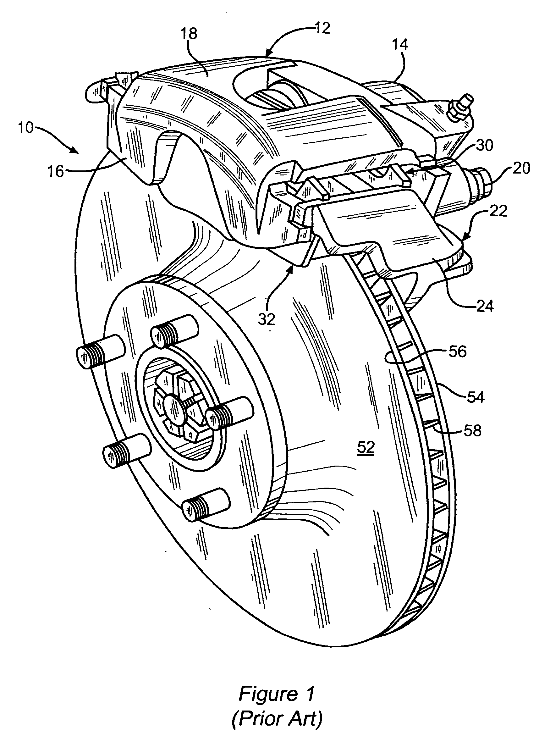
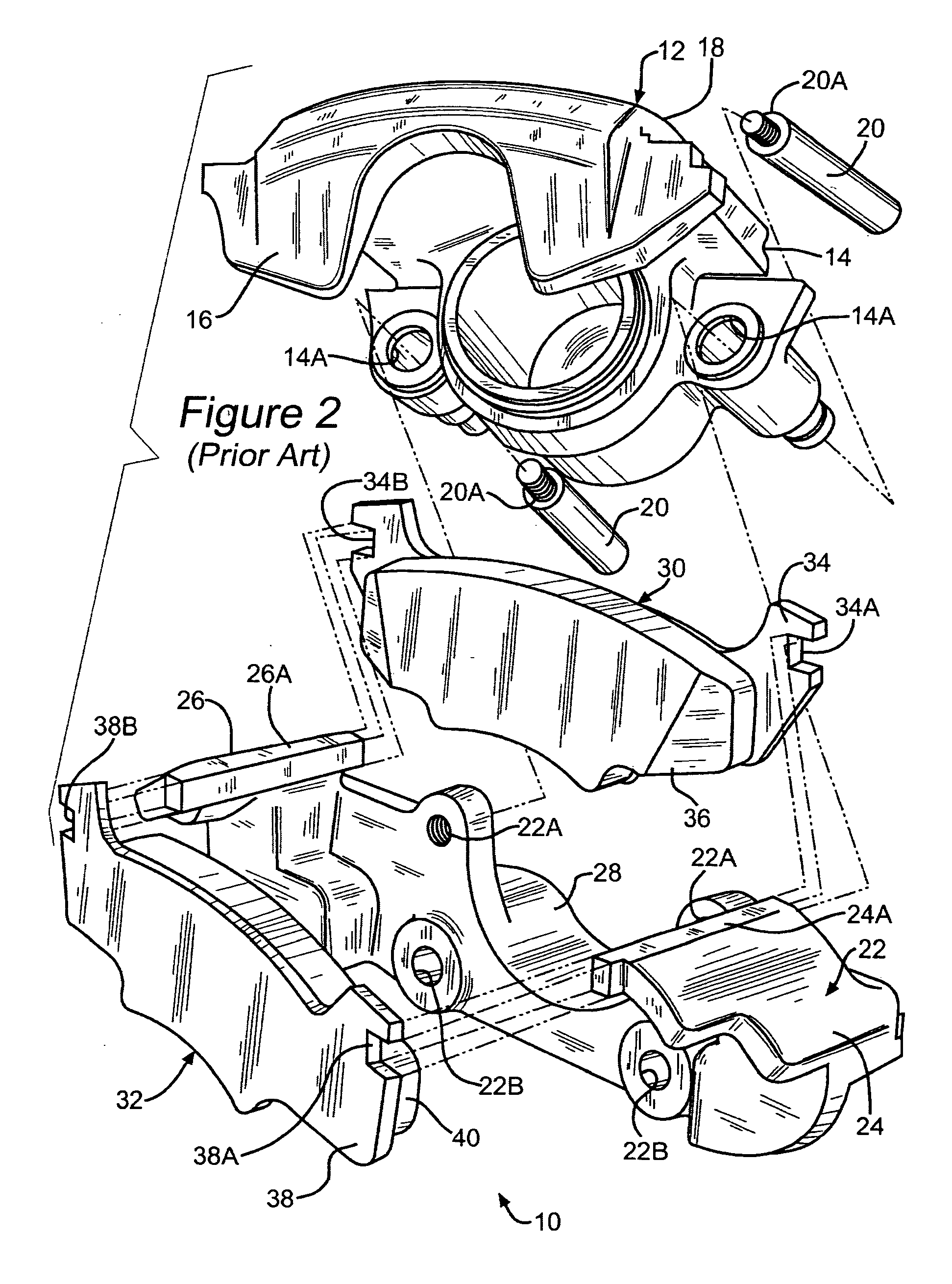
[0024] Referring now to the drawings, there is illustrated in FIGS. 1 through 3 a portion of a prior art vehicle disc brake assembly, indicated generally at 10. The general structure and operation of the prior art disc brake assembly 10 is conventional in the art. Thus, only those portions of the prior art disc brake assembly 10 that are necessary for a full understanding of this invention will be explained and illustrated. Although this invention will be described and illustrated in connection with the particular kind of vehicle disc brake assembly 10 disclosed herein, it will be appreciated that this invention may be used in connection with other kinds of disc brake assemblies if so desired.

[0025] As shown in prior art FIG. 1, the disc brake assembly 10 is a sliding type of disc brake assembly and includes a generally C-shaped caliper, indicated generally at 12. The caliper 12 includes an inboard wall portion 14 and an outboard wall portion 16, which are interconnected by an inte...


PUM


Abstract

A disc brake caliper for braking a wheel if a vehicle includes an inboard wall, an outboard wall spaced laterally from the inboard wall, each wall having a leading hole spaced a first distance on a first side from a lateral axis and extending through the respective wall, a trailing hole spaced a second distance on a second side opposite the first side from the lateral axis and extending through the respective wall, and a bridge interconnecting the inboard wall and the outboard wall.

Description

BACKGROUND OF THE INVENTION [0001] This invention relates in general to disc brake assemblies and in particular to an improved caliper for use in a disc brake assembly for a vehicle. [0002] Most vehicles are equipped with a brake system for slowing or stopping movement of the vehicle in a controlled manner. A typical brake system for an automobile or light truck includes a disc brake assembly for each of the front wheels and either a drum brake assembly or a disc brake assembly for each of the rear wheels. The brake assemblies are actuated by hydraulic or pneumatic pressure generated when an operator of the vehicle depresses a brake pedal. The structures of these drum brake assemblies and disc brake assemblies, as well as the actuators therefor, are well known in the art. [0003] A typical disc brake assembly includes a rotor, which is secured to the wheel of the vehicle for rotation therewith. A caliper assembly is supported on pins, which are secured to an anchor bracket. The ancho...

Claims


Application Information

Patent Timeline
IPC IPC(8): F16D65/14
CPCF16D55/225F16D2055/007F16D65/095
Inventor DEMORAIS, ANTONIO EDUARDOMILLER, HARRY
Owner KELSEY HAYES CO
Why Eureka
Try Eureka