Internal combustion engine provided with a heating device in a combustion chamber and a control method for the heating device

a technology of heating device and combustion chamber, which is applied in the direction of machines/engines, mechanical equipment, lighting and heating apparatus, etc., can solve the problems of inability to control the temperature of the glow plug, the temperature change in the combustion chamber, and the inability to withstand excessive thermal stress, etc., to reduce the preheating time of the heating device and maintain the temperature of the heating device. stable

Active Publication Date: 2006-12-28
FAB ITAL MAGNETI MARELLI SPA
View PDF8 Cites 18 Cited by
  • Summary
  • Abstract
  • Description
  • Claims
  • Application Information

AI Technical Summary

Benefits of technology

[0013] The object of the present invention is to provide an internal combustion engine provided with a heating device and a control method for the heating device, which makes it possible to reduce the preheating time of the heating device and, at the same time, ensures that the temperature of the heating device remains very stable in any operating condition of the engine.

Problems solved by technology

Although they reduce the preheating time of the glow plug, the electronic control systems discussed above have a number of drawbacks: first, the supply of an overvoltage to the glow plug may damage it when the initial conditions of the plug and the combustion chamber differ from the conditions set in the control; in practice, if the ignition, rather than taking place from a “cold” engine, takes place from a “hot” engine, i.e. at a temperature slightly lower than the working temperature, then the supply of an overvoltage to the glow plug may generate an extremely high temperature which is higher than the temperature that can be tolerated by the glow plug, thereby subjecting the latter to excessive thermal stresses which it is unable to withstand.
A second drawback lies in the fact that the open loop electronic control systems discussed above do not ensure that the plug temperature remains stable enough with variations of those of the engine operating parameters which to some extent cause a change of temperature in the combustion chamber.
In other words, the control of the glow plug temperature carried out by the above-mentioned electronic control systems is not very reliable as the temperature parameter to be controlled is conditioned by a number of engine parameters and by a number of environmental conditions to which the plug is exposed.
These self-regulating glow plugs have the drawback that they are subject to a degree of temperature dispersion in the various operating conditions of the engine; in practice, as the engine operating point varies there is a change in the heat exchange and the self-regulating glow plug is unable appropriately to adapt its heating power, and is thus subject to higher temperature variations.

Method used


Image

  • Internal combustion engine provided with a heating device in a combustion chamber and a control method for the heating device
  • Internal combustion engine provided with a heating device in a combustion chamber and a control method for the heating device
  • Internal combustion engine provided with a heating device in a combustion chamber and a control method for the heating device

Examples


Embodiment Construction

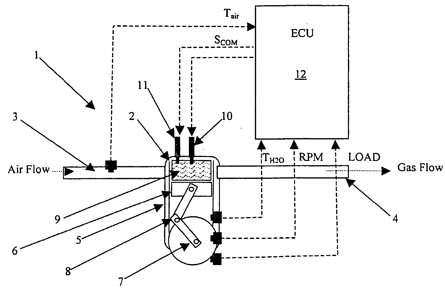
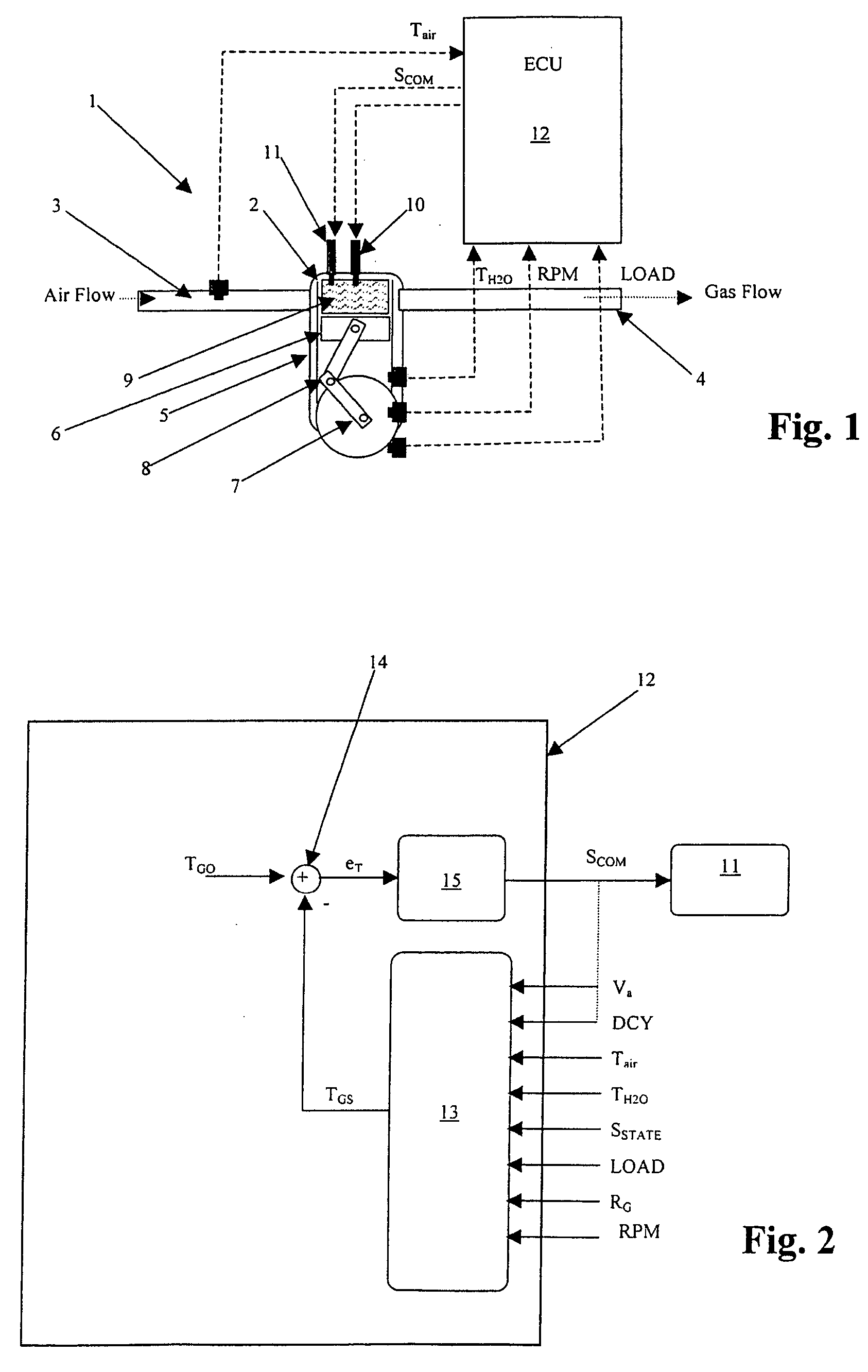
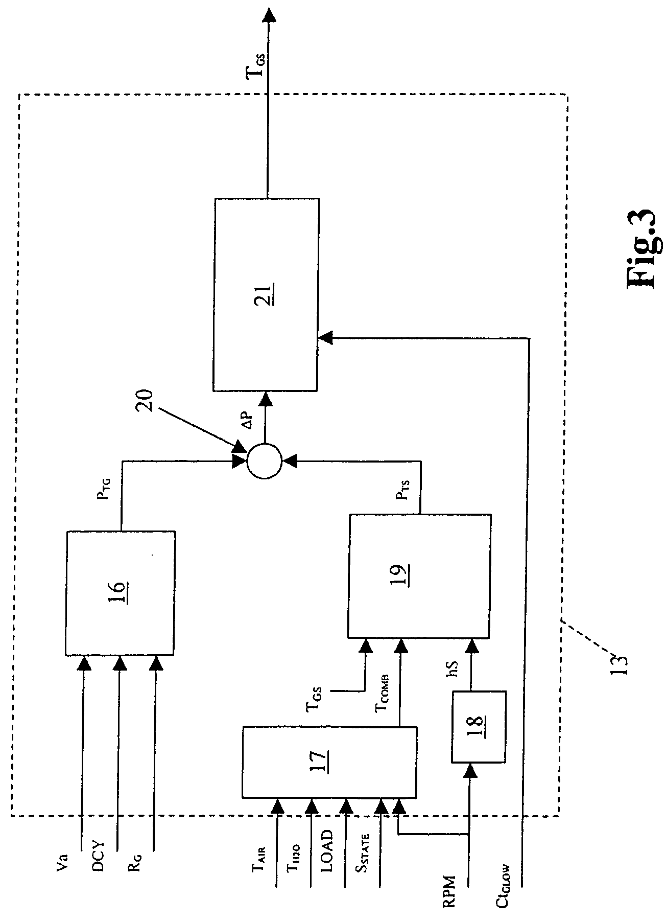
[0021] The principle on which the present invention is based is essentially that of carrying out a feedback control (i.e. a closed loop control) of the temperature of the heating device in a variable volume combustion chamber of an internal combustion engine, as a function of an estimation of the temperature of this heating device; this estimate is carried out using an energy balance model of the thermal powers generated and exchanged within the combustion chamber.

[0022] In other words, the present invention is based on the notion of estimating the temperature of the heating device on the basis of an energy balance between the thermal power developed by the heating device, and the thermal power exchanged between the combustion chamber and the operating fluid contained in this combustion chamber, and of driving the heating device as a function of the difference between the estimated temperature and an objective temperature which needs to be reached by the heating device in a particu...


PUM


Abstract

An internal combustion engine comprising at least one cylinder provided with at least one glow plug adapted to heat a variable volume combustion chamber within the cylinder, and an electronic control unit which in turn comprises an estimation module adapted to estimate the temperature of the glow plug within the combustion chamber and a control module which is adapted to drive the glow plug as a function of the estimated temperature.

Description

[0001] The present invention relates to an internal combustion engine provided with a heating device in a combustion chamber, and to a control method for the heating device. BACKGROUND OF THE INVENTION [0002] As is known, the combustion chambers of internal combustion engines, in particular diesel engines, are provided with heating devices, known typically as “glow plugs”, whose function is appropriately to heat the combustion chambers and the operating fluid in these chambers so as to ensure a certain efficiency of the combustion process, even in operating conditions which are not optimal, for instance at a low temperature of the combustion chamber and / or of the operating fluid. [0003] In internal combustion engines, one of the most critical of the operating conditions to which the combustion process is subject, and in which the use of glow plugs is required, is in particular the engine ignition phase. [0004] In this phase, in practice, the temperature of the combustion chamber is ...

Claims


Application Information

Patent Timeline
Patent Type & Authority Applications(United States)
IPC IPC(8): F23Q7/22F01M5/02
CPCF02P19/025F02D35/025
Inventor SERRA, GABRIELEDE CESARE, MATTEO
Owner FAB ITAL MAGNETI MARELLI SPA
Why Eureka
Try Eureka