Method and system for linking a wireless hand held optical reader with a base unit or other wireless device

a wireless hand-held optical reader and wireless technology, applied in the field of optical devices, can solve the problems of inability to scan large or heavy items, inability to move large and/or heavy objects inherently risky and undesirable, and inability to avoid inadvertent communication, reduce the risk of inadvertent linking, and eliminate unnecessary steps

Active Publication Date: 2006-12-28
HAND HELD PRODS
View PDF28 Cites 73 Cited by
  • Summary
  • Abstract
  • Description
  • Claims
  • Application Information

AI Technical Summary

Benefits of technology

[0012] It would thus be desirable in some instances to have a wireless optical device configured to operate in a plurality of user-selectable modes for linking a wireless hand held optical reader with either a base unit or other wireless device. For example, for an application at a cash register, it is necessary that the base unit associated with that particular cash register only receive data from hand held optical readers intentionally linked with that base unit and not from other hand held readers operating at different cash registers. In order to avoid any inadvertent communication between a wireless hand held optical reader from one cash register and a base unit from another cash register, the hand held optical reader is configured in a “reader-base linking mode” that requires a cashier to temporarily physically couple the optical reader and base unit together in order to initiate the linking process, which is then completed wirelessly between the devices. Requiring this temporary physical coupling between the two devices to initiate the linking reduces the risk of any inadvertent linking. Furthermore, initiating the linking process using a step, i.e., placing the hand held optical reader into the base unit, that is required for charging the optical reader anyway, eliminates unnecessary steps and makes use of the optical reader more convenient. In addition, completing the linking process wirelessly, allows the user to confirm that the hand held optical reader and base unit are communicating properly prior to performing any scanning operations.

Problems solved by technology

While stationary presentation-type optical readers may be adequate for scanning encoded optical indicia on small items that are easily moved through their field of view by a cashier or other operator, these types of optical readers are not well suited for scanning large or heavy items that need to be repositioned by the cashier or customer so the scanner can read the optical indicia.
This movement of large and / or heavy objects is inherently risky and undesirable.
Furthermore, since stationary presentation-type optical readers require that the cashier position the item to be scanned somewhat precisely into the field of view of the optical reader so that the optical reader can scan the optical indicia, multiple attempts are often required to achieve a successful scan.
This can lead to frustration by the cashier and customer and thus detract from customer satisfaction.
Unfortunately, this approach does not eliminate the problems associated with scanning items that are out of reach of the hardwired hand held optical reader and must be repositioned into the field of view of the optical reader so that the optical reader can scan the optical indicia.
While each of these prior art linking approaches increase the flexibility of the hand held optical reader systems over systems where the optical reader is permanently linked with a base unit, these approaches still have several disadvantages which limit the flexibility of the hand held optical reader to be used as an input device.
The approach whereby the hand held optical reader is linked using only the mating electrical connectors of the optical reader and base unit does not allow for confirmation that the radios in the devices are communicating or for linking between the hand held optical reader and other wireless devices that do not have mating electrical connectors.

Method used


Image

  • Method and system for linking a wireless hand held optical reader with a base unit or other wireless device
  • Method and system for linking a wireless hand held optical reader with a base unit or other wireless device
  • Method and system for linking a wireless hand held optical reader with a base unit or other wireless device

Examples


Embodiment Construction

[0036] Reference will now be made in detail to the present preferred embodiments of the invention, examples of which are illustrated in the accompanying drawings. Whenever possible, the same reference numerals will be used throughout the drawings to refer to the same or like parts for clarity.

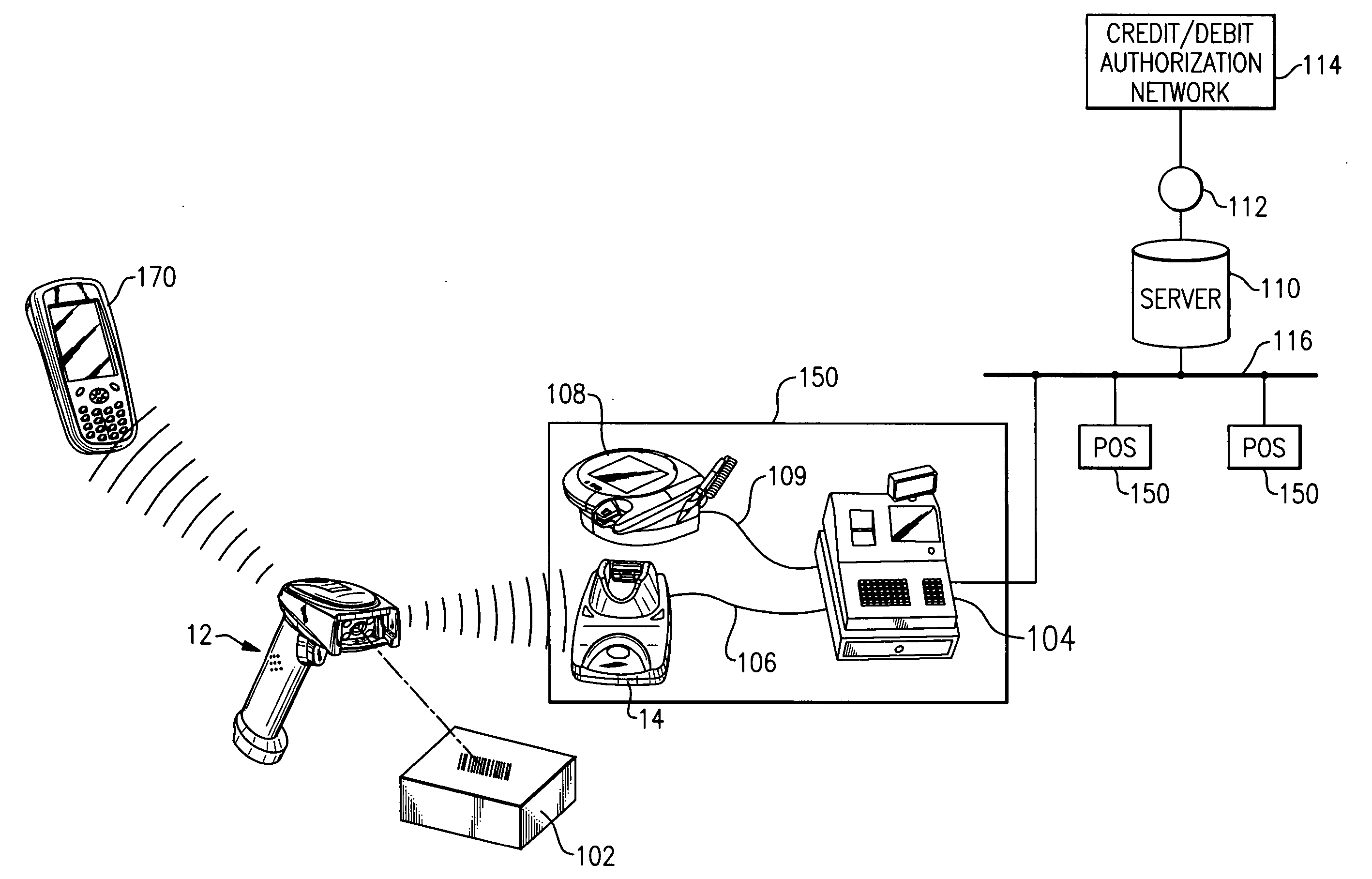
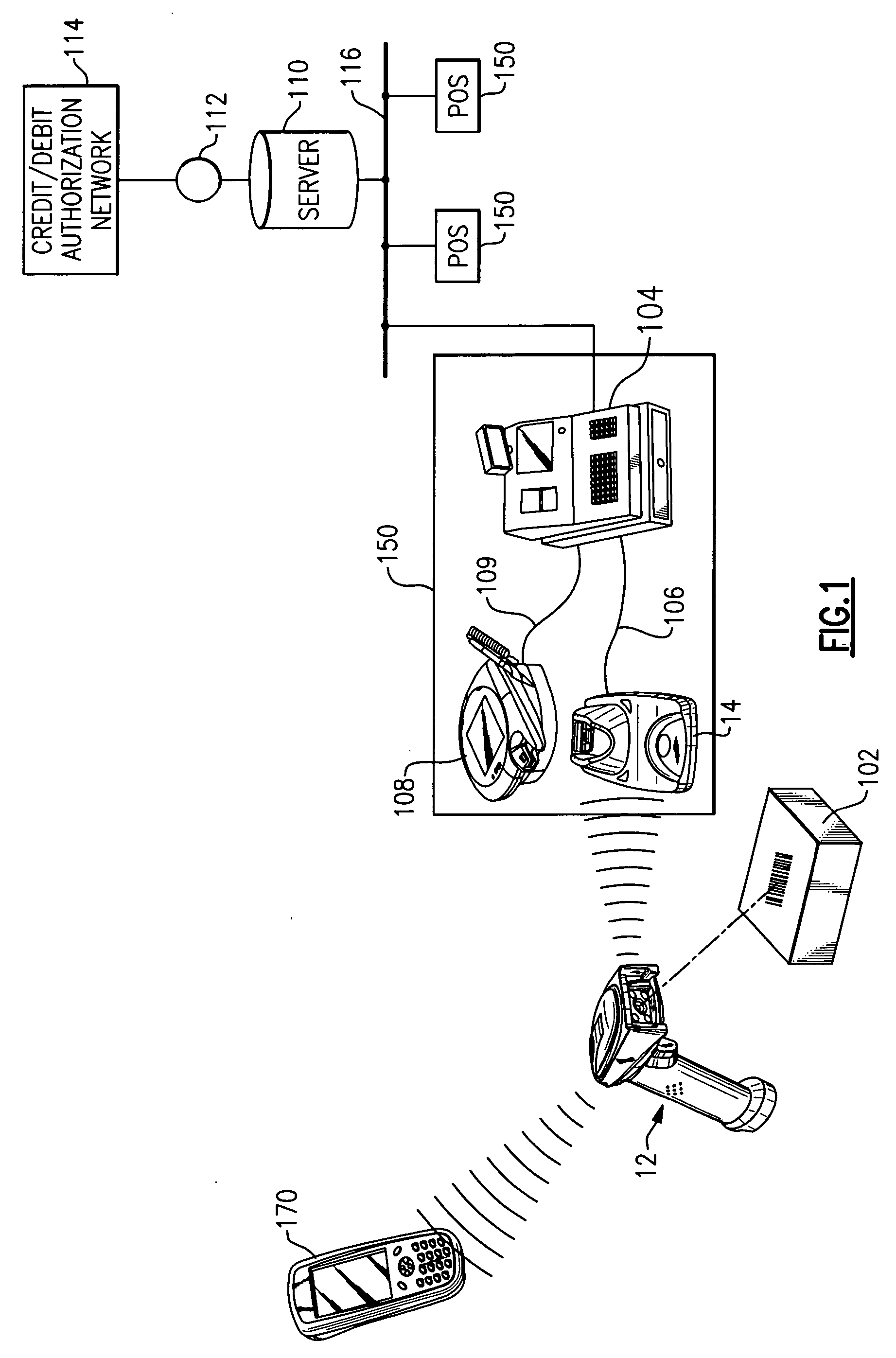
[0037] As shown in FIG. 1, the present invention can be used as part of a retail store network 100 at a point of sale (POS) 150. In the illustrative retail store network 100 of FIG. 1, the hand held optical reader 12 scans an item's 102 bar code symbol, decodes the information contained in the bar code symbol, and wirelessly communicates the decoded bar code data associated with that item 102 to the base unit 14 linked with the hand held optical reader 12. The base unit 14 then communicates that bar code data message to a host device such as a cash register 104, which can also be located at the point of sale 150. The base unit 14 communicates this bar code data message to the cash register 104...


PUM


Abstract

A retail store network comprising a cash register, server, and hand held optical reader for reading a bar code symbol of an item and generating a decoded out bar code data message. The hand held bar code reader has an electrical connector and a wireless transceiver. The optical reader can be used with a base unit also having an electrical connector and a wireless transceiver. The network is configured so that the hand held bar code reader and the base unit have one linking mode in which the address of the base unit is sent to the hand held bar code reader through their respective electrical connectors. The linking process is completed by way of wireless communication, including the transmission of the address of the hand held bar code reader to the base unit. The hand held bar code reader further comprises circuitry to allow the optical reader to also operate in a linking mode where it can link with other devices that it cannot physically mate its electrical connector with, but can initiate the linking and complete the process wirelessly.

Description

BACKGROUND OF THE INVENTION [0001] 1. Field of the Invention [0002] The present invention relates to optical devices in general, and more particularly, to the linking of a wireless hand held optical reader with a base unit or other wireless device. [0003] 2. Technical Background [0004] In various commercial and industrial environments, the use of optical indicia, such as bar code symbols, has become the norm for identifying products and inventory. Typically, each item is marked with optical indicia associated with a description of the item and other attributes (for example, price) that are stored in a database of a host device or network system. Optical readers are used to read the optical indicia and provide that reading as input information to host devices. In some cases, the data is provided to the host devices via base units, which communicate with the optical reader. Examples of host devices include a computer (fixed or portable), a personal digital assistant (PDA), a portable ...

Claims


Application Information

Patent Timeline
Patent Type & Authority Applications(United States)
IPC IPC(8): G06K7/10G06K15/00
CPCG06K7/10881
Inventor ROBINSON, MICHAEL D.IZZO, JOHNLIVINGSTON, JOSEPHROBERTS, CLAYTONWALCZYK, JOSEPH A.
Owner HAND HELD PRODS
Why Eureka
Try Eureka