
Vehicle occupant knee protection apparatus

Inactive Publication Date: 2006-12-28
HONDA MOTOR CO LTD
View PDF0 Cites 6 Cited by
  • Summary
  • Abstract
  • Description
  • Claims
  • Application Information

AI Technical Summary

Benefits of technology

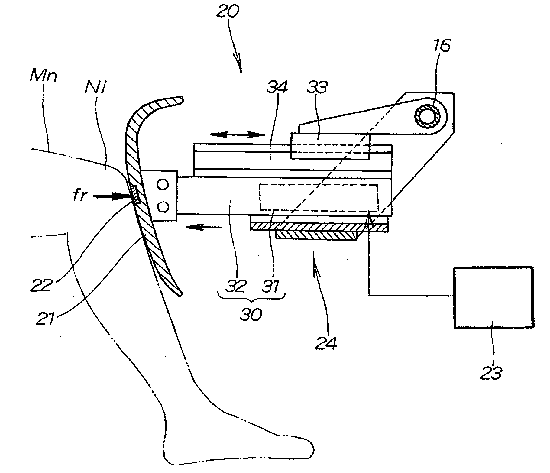
[0013] The present invention provides an occupant knee protection apparatus for a vehicle to protect the knees of an occupant when collision energy acts on the vehicle, the apparatus comprising a knee protection member that is disposed in an opposable position to knees of the occupant seated in a vehicle seat, and that reduces collision energy that acts on the knees; a contact force detector for detecting the contact force of the knees against the knee protection member; a controller for issuing a control signal so as to reduce the contact force to a force control target value set in advance and to maintain the reduced value, on the basis of a detection signal of the contact force detector; and a drive unit for moving the knee protection member in the front / rear direction of the vehicle in accordance with the control signal of the controller.
[0015] More specifically, in the occupant knee protection apparatus for a vehicle, a contact force can be rapidly and reliably reduced to a force control target value, and the reduced value can be maintained. Stabilized energy-absorbing performance by the knee protection member can therefore be adequately assured. As a result, the load on the knees and thighs of the occupant can be further reduced in an adequate manner. The forward movement distance of the occupant can be reduced because the contact force that has been reduced to the force control target value can be kept at the reduced value.
[0016] Furthermore, the knee protection member does not move toward the knees prior to collision energy acting on the vehicle. For this reason, the occupant does not feel annoyance under ordinary conditions, and comfort can be maintained.
[0018] The knee protection member is retracted from the knees by an actuator when the contact force is large. In this case, the driving force of the actuator may be supplemented by a damper. The maximum driving force of the actuator can be reduced by configuring the structure in this manner. Drive performance can be assured by using a compact, low-cost actuator having a low driving force. For this reason, the contact force can be controlled with good efficiency.
[0020] In this manner, overshooting (going too far) can be sufficiently controlled when the contact force is reduced to the force control target value because the contact force is reduced by being divided into two-tier target values of small and large magnitudes. Therefore, in an actual collision, the contact force can be reduced to the force control target value in a short period of time even during considerable disturbance when the deceleration of the vehicle varies or conditions otherwise change after collision energy has acted on the vehicle. As a result, energy can be uniformly absorbed beginning at the point at which the knees of the occupant move forward and make contact with the knee protection member, and ending at the point at which the contact force is reduced and maintained at the force control target value. Stabilized energy-absorbing performance by the knee protection member can be more adequately assured.

Problems solved by technology

In an actual collision, the deceleration of the vehicle 101 after collision energy has acted on the vehicle is not necessarily fixed and often varies in a complicated manner.

Method used


Image

  • Vehicle occupant knee protection apparatus
  • Vehicle occupant knee protection apparatus
  • Vehicle occupant knee protection apparatus

Examples


Embodiment Construction

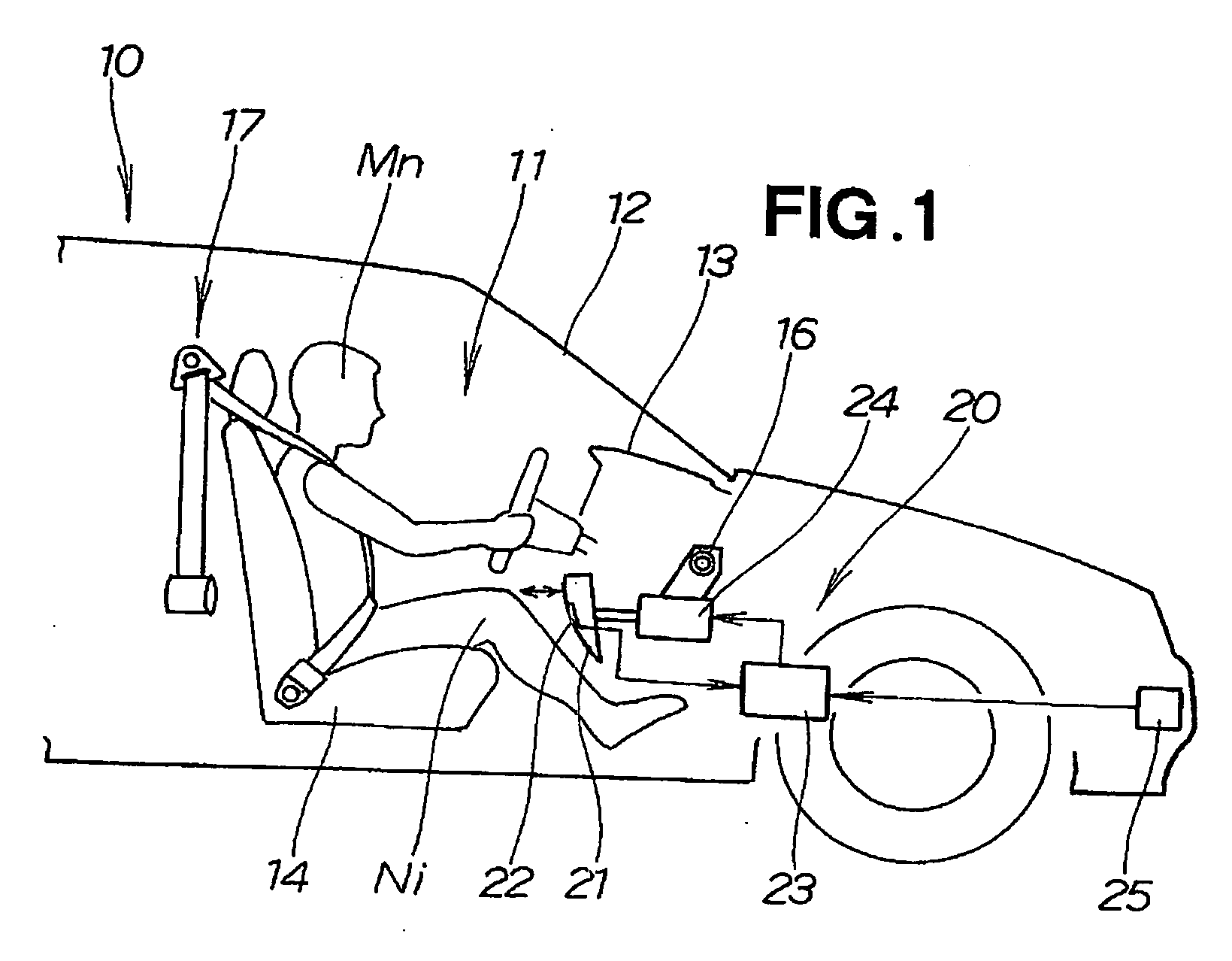
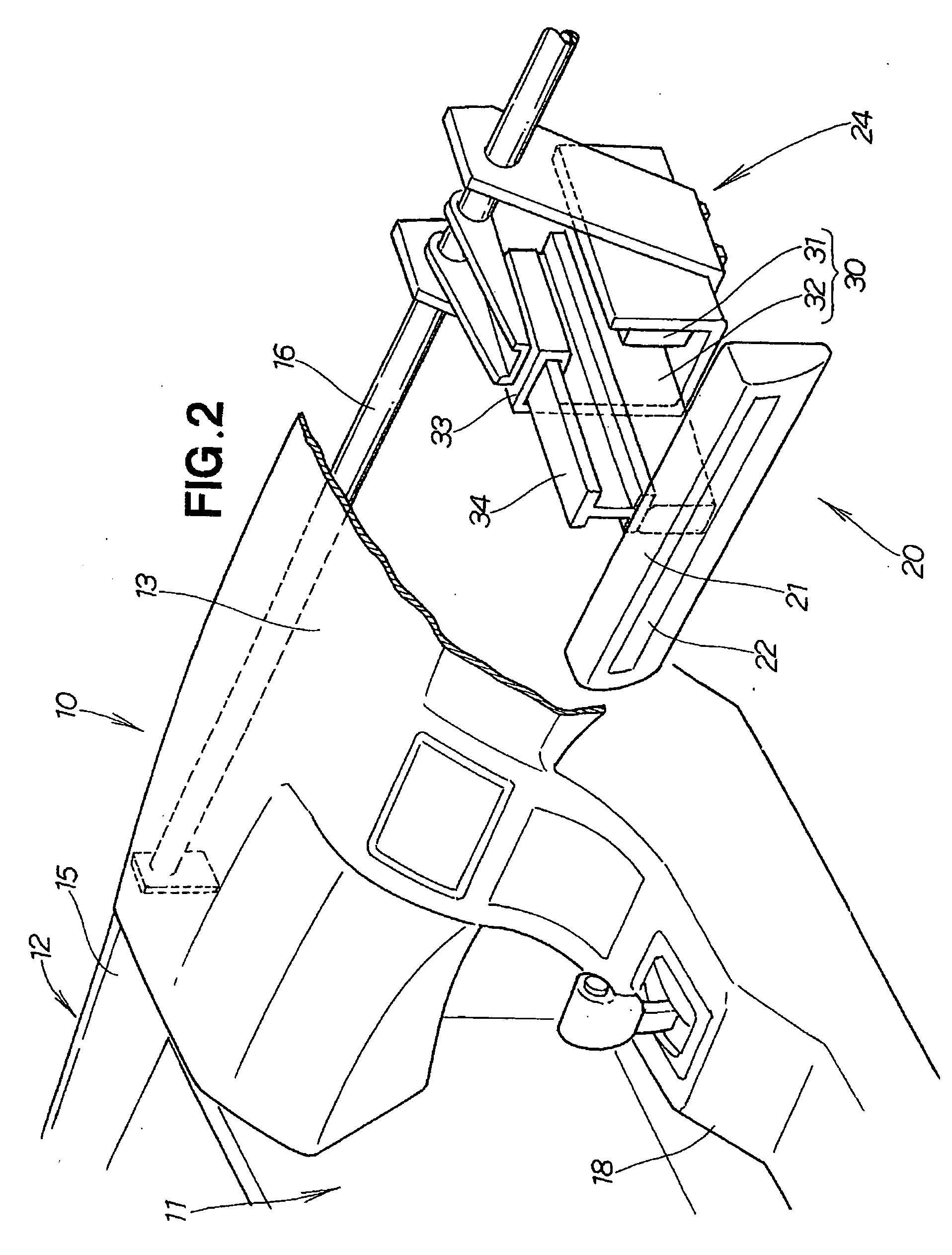
[0032] A vehicle 10 is provided with an instrument panel 13 mounted on a vehicle body 12 in the front area of a vehicle interior 11, an occupant knee protection apparatus 20, and an acceleration sensor 25, as shown in FIGS. 1 and 2.

[0033] The instrument panel 13 is disposed in front of the occupant Mn seated in a seat 14, and is provided with an occupant knee protection apparatus 20 for protecting the left and right knees Ni of the occupant Mn. The occupant Mn is the driver seated in the driver's seat 14, for example.

[0034] The vehicle body 12 has a fixed bar 16 suspended between the left and right front pillars 15 the further forward on the vehicle body than the instrument panel 13. The fixed bar 16 is a round pipe, round rod, or another rod-shaped fixed member that extends parallel to the width direction of the vehicle. The vehicle 10 is provided with a console box 18 and a seat belt apparatus 17 for restraining the seated occupant Mn.

[0035] The occupant knee protection apparat...


PUM


Abstract

A vehicle occupant knee protection apparatus for protecting the knees of an occupant when collision energy acts on a vehicle. The occupant knee protection apparatus comprises a knee protection member, a contact force detector, a controller, and a drive unit. The knee protection member is disposed in an opposable position to knees of an occupant seated in a vehicle seat. The contact force detector detects the contact force of the knees on the knee protection member. The controller performs control that reduces the contact force to a force control target value and that maintains the reduced value. The drive unit moves the knee protection member in the front / rear direction of the vehicle on the basis of an output signal from the controller.

Description

FIELD OF THE INVENTION [0001] The present invention relates to a vehicle occupant knee protection apparatus whereby knees are protected by mitigating collision energy that acts on the knees of a vehicle occupant in a collision. BACKGROUND OF THE INVENTION [0002] In recent years, progress has been made in the development of occupant protection apparatuses for protecting occupants when collision energy acts on a vehicle. As a part of this type of occupant protection, efforts are being made to develop an occupant knee protection apparatus for a vehicle whereby knees are protected by mitigating collision energy that acts on the knees of an occupant. [0003] For example, efforts are being made to develop occupant knee protection apparatuses for a vehicle provided with a passive energy-absorbing structure that has a knee protection member in the front area of the vehicle interior. When collision energy acts on the vehicle from the front direction, the knees of the occupant move forward due...

Claims


Application Information

Patent Timeline
IPC IPC(8): B60R21/045B60R21/04
CPCB60R2021/0051B60R21/045
Inventor MOTOZAWA, YASUKIFUJII, DAISUKENISHIMURA, HIDEKAZUAMANO, YOICHI
Owner HONDA MOTOR CO LTD
Learn More