
Automotive childproof safety lock control apparatus

a technology for controlling apparatus and childproof locks, which is applied in the direction of passenger lock actuation, electrical locking circuit, lock application, etc., can solve the problems of increasing production costs, inconvenient use, and childproof safety lock units cannot be put into the locking state once, and achieve the effect of opening quickly

Inactive Publication Date: 2006-12-28
MITSUI KINZOKU ACT
View PDF15 Cites 14 Cited by
  • Summary
  • Abstract
  • Description
  • Claims
  • Application Information

AI Technical Summary

Benefits of technology

[0011] The invention was made in view of the problem and an object thereof is to provide an automotive childproof safety lock control apparatus in which the operability of the childproof safety lock unit is improved.
[0012] Further, the invention provides an automotive childproof safety lock control apparatus which enables both the control of the childproof safety lock unit and the release of the door latch from the latching state by a single drive unit, so that a reduction in production costs can be realized.
[0013] Further, the invention provides an automotive door latch control apparatus with which the door can be opened quickly when the lock unit is in the locking state.

Problems solved by technology

Due to this, in the event that the childproof safety lock unit is failed to be controlled into a locking state before the vehicle starts, the childproof safety lock unit cannot be put into the locking state once the vehicle has started running.
Consequently, the driver and the occupants have to open and close the door while being conscious about the state of the childproof safety lock unit, and thus, the control apparatus has a problem that it is inconvenient for use.
However, when designed in such a way, there are necessary two actuators, one for controlling the childproof safety lock unit and the other for releasing the door latch from the latching state, producing another problem that an increase in production costs is called for.
Further, in the control apparatus disclosed in JP-A-11-166338 above, however, in order to release the door latch from the latching state when the lock unit is in the locking state, the control handle has to be controlled twice, and hence, the door cannot be opened quickly.

Method used


Image

  • Automotive childproof safety lock control apparatus
  • Automotive childproof safety lock control apparatus
  • Automotive childproof safety lock control apparatus

Examples


Embodiment Construction

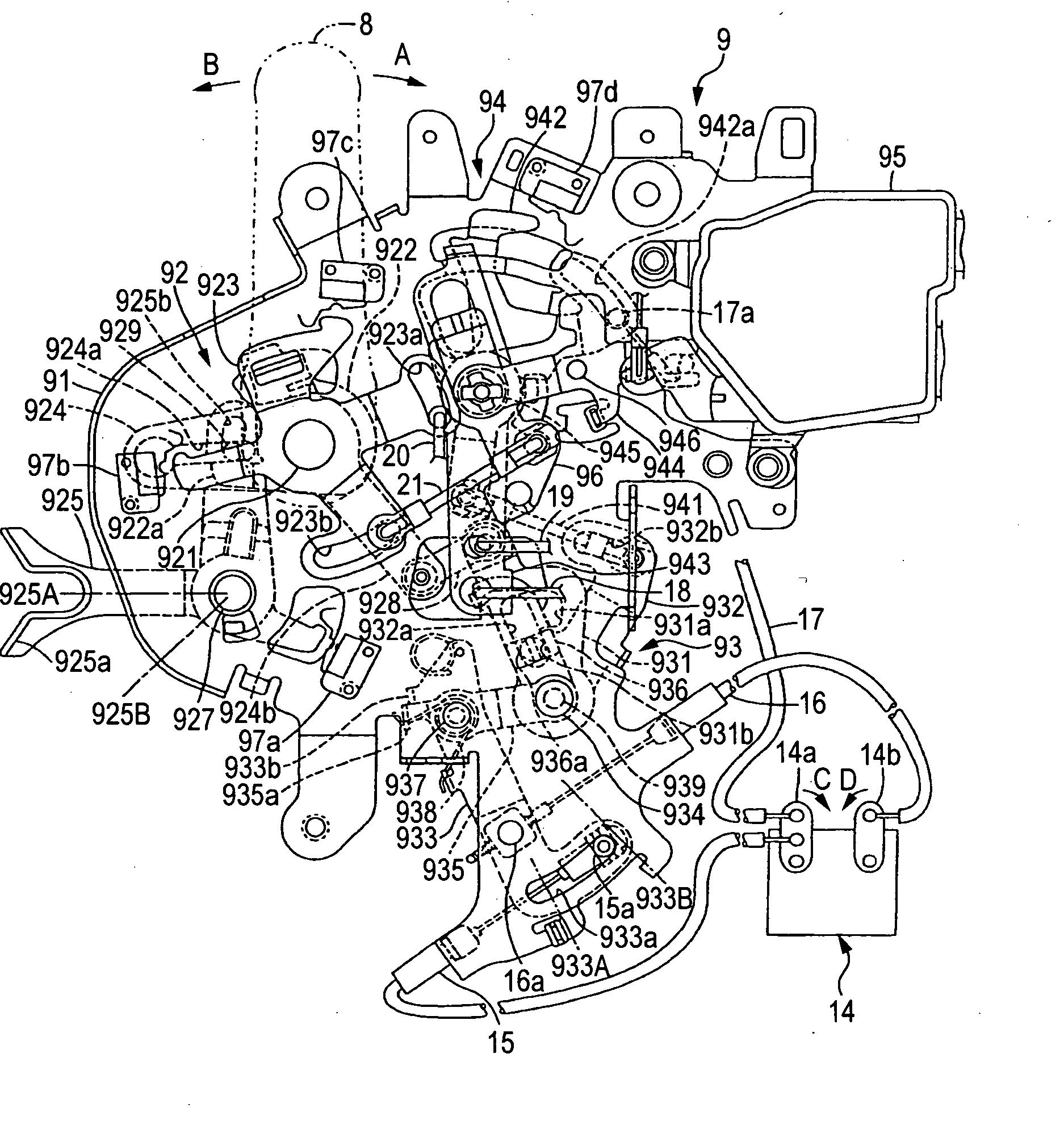
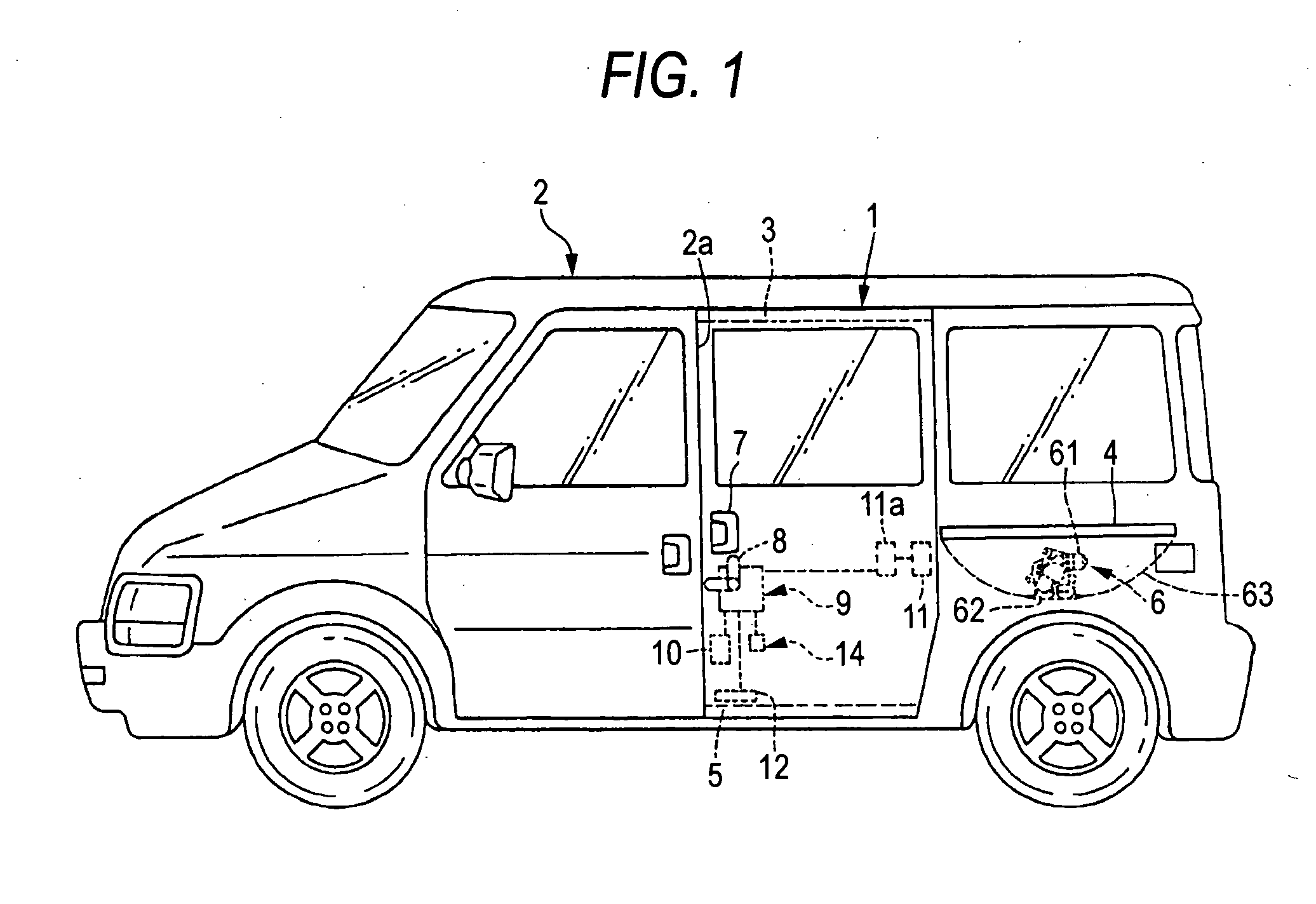
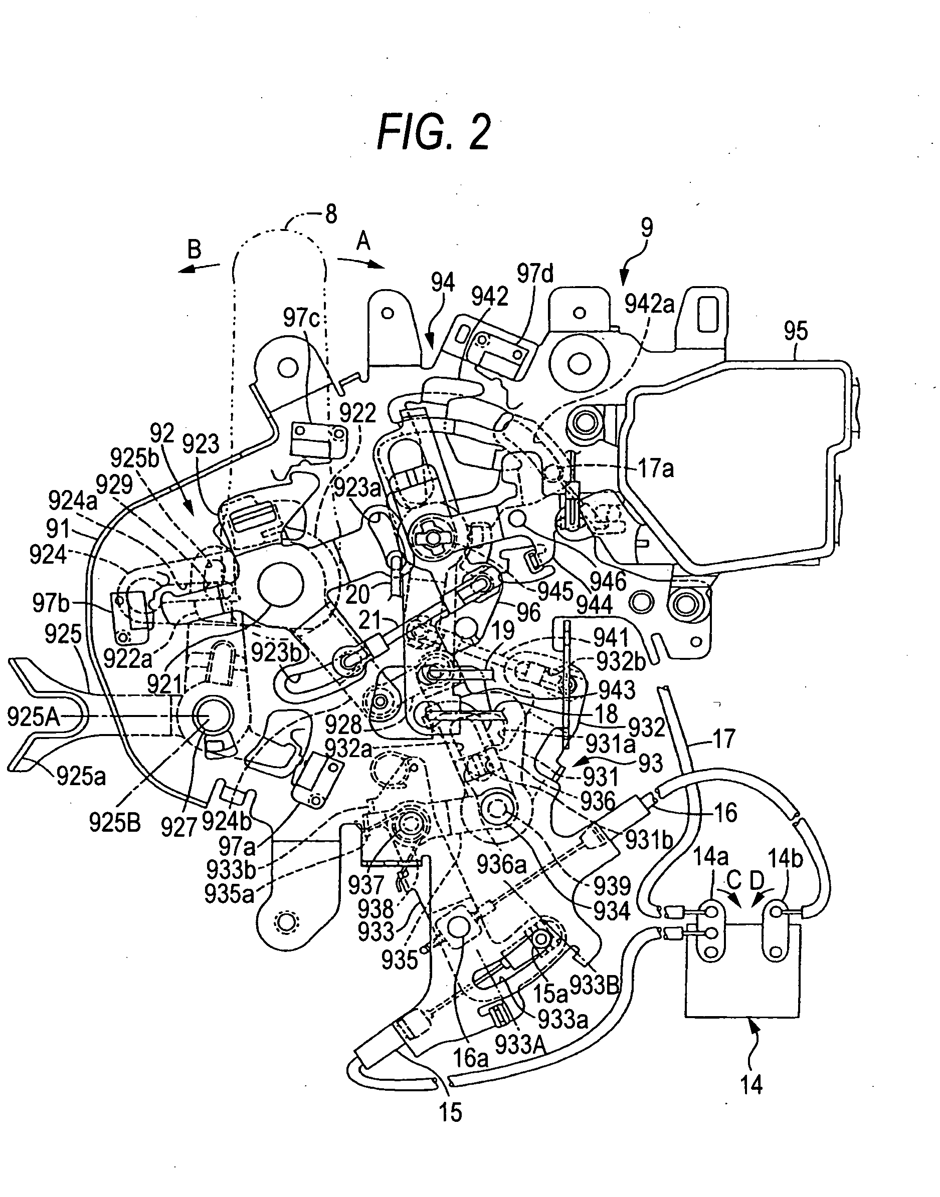
[0045] Hereinafter, an embodiment of the invention will be described based on the drawings. FIG. 1 is a side view of a vehicle to which the invention is applied, FIG. 2 is a side view of a control unit, FIG. 3 is a backside view of the control unit, and FIGS. 4 to 10 are control unit operation explaining drawings which show respective states of the unit. In a description which will be made below, the left in FIGS. 1, 2 and 4 to 10 and the right in FIG. 3 are regarded as facing the “front” of the vehicle, and the right in FIGS. 1, 2 and 4 to 10 and the left in FIG. 3 are regarded as facing the “rear” of the vehicle.

[0046] As shown in FIG. 1, a rear side sliding door (1) for a rear seat of a minivan or station wagon type of vehicle is supported in such a manner as to be moved to open from a totally closed position where the door closes an ingress and egress opening (2a) provided in a side of a body (2) to a totally opened position resulting when the door is totally moved rearwards al...


PUM


Abstract

An automotive childproof safety lock control apparatus including a door latch which can hold a door of a vehicle in a closed position, a childproof safety lock unit which can be displaced to an unlocking state where the release of the door latch from a latching state is enabled by controlling an inner handle provided inside of the vehicle to open the door and a locking state where the release of the door latch from the latching state is disabled, and a drive unit which is linked to the childproof safety lock unit and the door latch so as to displace the childproof safety lock unit from the locking state to the unlocking state and release the door latch from the latching state when activated in one direction and to displace the childproof safety lock unit from the unlocking state to the locking state when activated in the other direction.

Description

[0001] This application is based on Japanese Patent Applications No. 2005-183757, 2005-183758 and 2005-183759, which are incorporated herein by reference. BACKGROUND OF THE INVENTION [0002] 1. Field of the Invention [0003] The present invention relates to an automotive childproof safety lock control apparatus including a childproof safety lock unit which can be displaced to an unlocking state where a release of a door latch from a latching state through a door opening control by an inner handle provided inside a vehicle can be enabled and a locking state where the release can be disabled. [0004] The present invention also relates to an automotive door latch control apparatus which includes a lock unit which can be displaced to an unlocking state where the lock unit can transmit a door opening control force applied by a control handle provided on a door to a door lock and a locking state where the lock unit cannot transmit the door opening control force. [0005] 2. Description of the ...

Claims


Application Information

Patent Timeline
Patent Type & Authority Applications(United States)
IPC IPC(8): E05C3/06
CPCE05B77/26E05B81/64E05B81/16E05B81/06Y10T70/7062Y10T292/1047
Inventor WATANABE, MITSUHIROOGINO, MIKI
Owner MITSUI KINZOKU ACT
Learn More