Device for self-determination position of a robot

Inactive Publication Date: 2006-12-28
ECOVACS ROBOTICS (SUZHOU ) CO LTD
View PDF4 Cites 56 Cited by
  • Summary
  • Abstract
  • Description
  • Claims
  • Application Information

AI Technical Summary

Problems solved by technology

In the existing art, a robot (for example an autonomous vacuum cleaner) is able to autonomously avoid obstacles when moving in a defined area, yet it is a difficult problem to solve for the robot to judge its own coordinate position and keep moving along a

Method used


Image

  • Device for self-determination position of a robot
  • Device for self-determination position of a robot
  • Device for self-determination position of a robot

Examples


embodiment 1

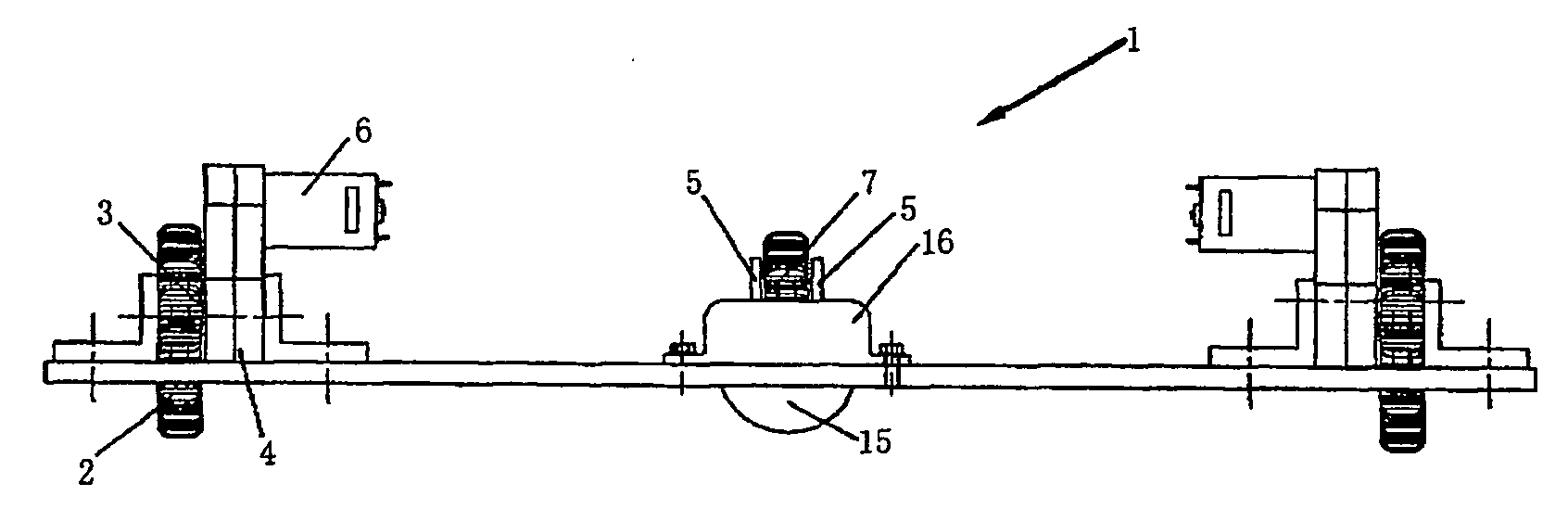
[0028]FIG. 1 is a front plan view of the present invention of Embodiment 1. The two opposed sides of the rolling wheel 14 have symmetrical configurations, thus only left side is illustrated for detailed description.

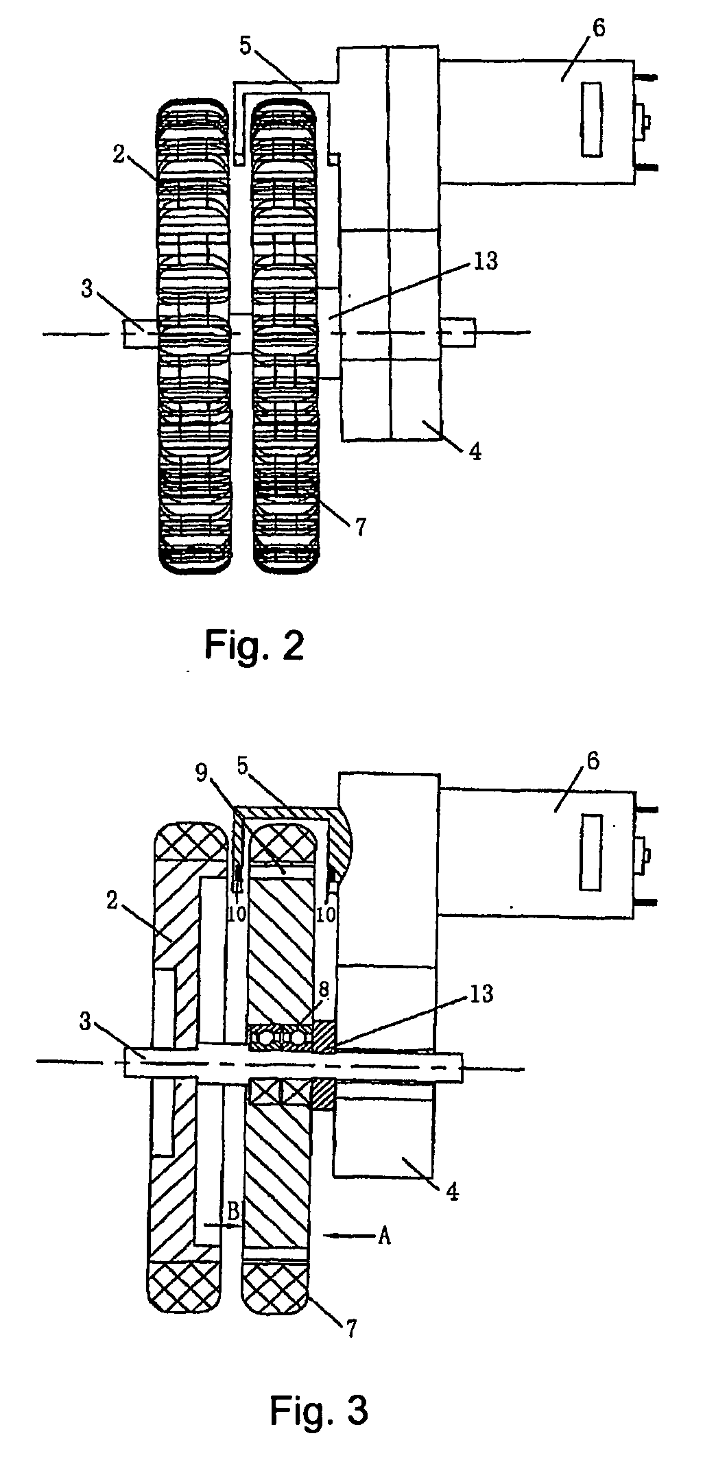
[0029] Referring to FIG. 1, FIG. 2 and FIG. 3, the left side of the device includes driving wheel 2, driven wheel 7, decelerator 4 and motor 6 in the sequence from outside to inside.

[0030] The driving wheel 2 is fixed to the wheel shaft 3. The wheel shaft 3 is connected to the power output portion of the decelerator 4. The power input portion of the decelerator 4 is connected to the outputting shaft of the motor 6. Thus the motor 6 drives the wheel shaft 3 to rotate and further causes the driving wheel 2 to rotate as well.

[0031] The driven wheel 7 is rotatably arranged on the wheel shaft 3 of the driving wheel 2 by a bearing 8 and is also fixed between the projecting part and the shaft sheath 13. The driven wheel 7 is arranged coaxially with the driving wheel 2 and the...

embodiment 2

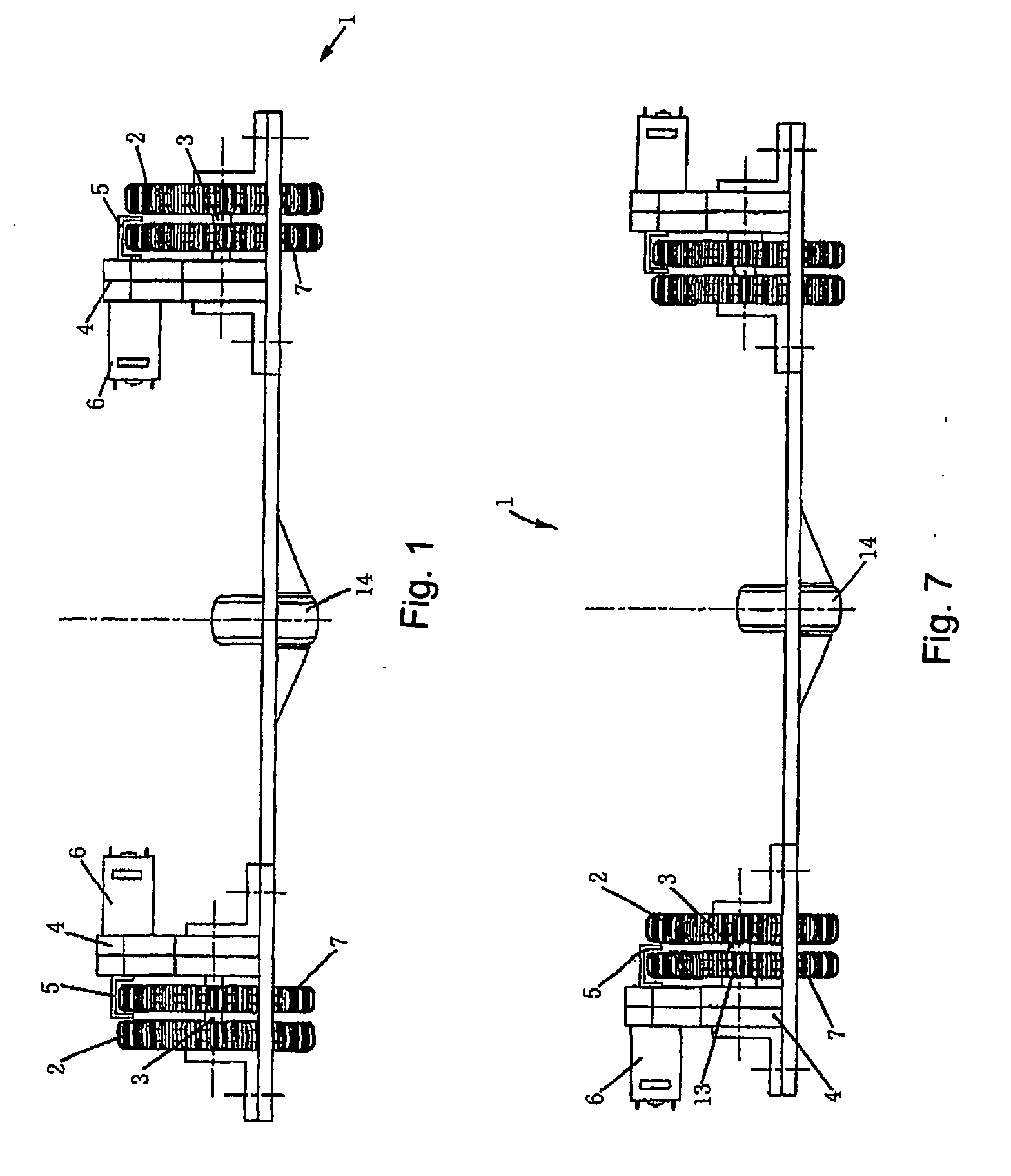
[0034]FIG. 7 is a front plan view of the present invention of Embodiment 2. The configuration of the device in Embodiment 2 is the same with that in Embodiment 1 except for that the arrangement sequence of components on two sides of the rolling wheel 14 in Embodiment 2 is reverse to the arrangement sequence of components in Embodiment 1. Taking the left side of the device as an example, the left side of the device includes a motor 6, a decelerator 4, driven wheels 7 and driving wheels 2 in the sequence from outside to inside.

embodiment 3

[0035]FIG. 8 is a bottom plan view of the present invention of Embodiment 3. The two opposed sides of the rolling wheel 14 have symmetrical configurations, thus only left side is illustrated for detailed description.

[0036] Referring FIG. 8, the front portion of the left side of the device is provided with a driven wheel means and the rear portion is provided with a driving wheel means. The rear portion includes a driving wheel 2, a decelerator 4 and a motor 6 in the sequence from outside to inside. The driving wheel 2 is fixed to the wheel shaft 3, which drives the driving wheel 2 to rotate as the wheel shaft 3 rotates. The decelerator 4 is arranged immediately adjacent to the driving wheel 2 and is connected to the wheel shaft 3. The motor 6 is connected to the power input portion of the decelerator 4 through the outputting shaft.

[0037] The driven wheel 7, having a same diameter with that of driving wheel 2, is arranged on the robot body 1 and moves as the robot body 1 moves, its...


PUM


Abstract

The present invention relates to a device of self-determination position of a robot, and said device includes: a robot body; at least two driving wheels locating in two opposed sides of the robot body; a decelerator, connecting with a wheel shaft of said driving wheels through a power inputting portion; a motor, connecting with said power inputting portion of the decelerator through an outputting shaft; at least two driven wheels providing on the robot body, on which there are a plurality of grids around circumference direction taking the wheel shaft as the center; and at least two pairs of sensors, locating in one of outsides of each driven wheels, respectively, wherein said each pair of sensors include an emitting part and a receiving part facing toward said emitting part, moreover, through said grids, said receiving part can receive signals sent from the emitting part. According to the present invention, when said driving wheels lose steps or slip, the driven wheels do not move in respect to the ground, so that said sensors would not output signals about rotation of the wheels. It therefore can really represent the movement relation between said robot body and the ground.

Description

FIELD OF INVENTION [0001] The present invention relates to a position-determining device, especially a device for self-determination position of a robot. BACKGROUND OF INVENTION [0002] In the existing art, a robot (for example an autonomous vacuum cleaner) is able to autonomously avoid obstacles when moving in a defined area, yet it is a difficult problem to solve for the robot to judge its own coordinate position and keep moving along a defined path. Most robots adopt the autonomous navigation and calculation method so as to move according to a virtual house map. The navigation and calculation method includes: measuring the rotation angle of driving wheels of the robot, utilizing a traditional axle-direction encoder to output the rotation angle so as to reflect the displacement of the robot relative to the ground, building an electric map, navigating and moving according to the electric map. However, this technology does not preclude the situations of wheels losing steps or slippin...

Claims


Application Information

Patent Timeline
IPC IPC(8): G01C22/00B25J5/00B25J13/08G01D5/347
CPCB25J5/007G01D5/3473B25J13/088
Inventor QIAN, DONGQI
Owner ECOVACS ROBOTICS (SUZHOU ) CO LTD
Why Eureka
Try Eureka