Mobile robot and a method for calculating position and posture thereof

a mobile robot and position calculation technology, applied in the direction of process and machine control, distance measurement, instruments, etc., can solve the problems of increasing the cost, and affecting the accuracy of calculating the position of the mobile robo

Inactive Publication Date: 2006-12-28
KK TOSHIBA
View PDF24 Cites 125 Cited by
  • Summary
  • Abstract
  • Description
  • Claims
  • Application Information

AI Technical Summary

Benefits of technology

[0009] The present invention is directed to a mobile robot and a method for accuratel

Problems solved by technology

In this case, the cost increases and its appearance is undesirable.
In case of detecting the marker from a camera image, it takes a long time for the robot to previously search many markers in the environment.
Accordingly, a user must previously input accu

Method used


Image

  • Mobile robot and a method for calculating position and posture thereof
  • Mobile robot and a method for calculating position and posture thereof
  • Mobile robot and a method for calculating position and posture thereof

Examples


Embodiment Construction

[0028] Hereinafter, various embodiments of the present invention will be explained by referring to the drawings. The present invention is not limited to the following embodiments.

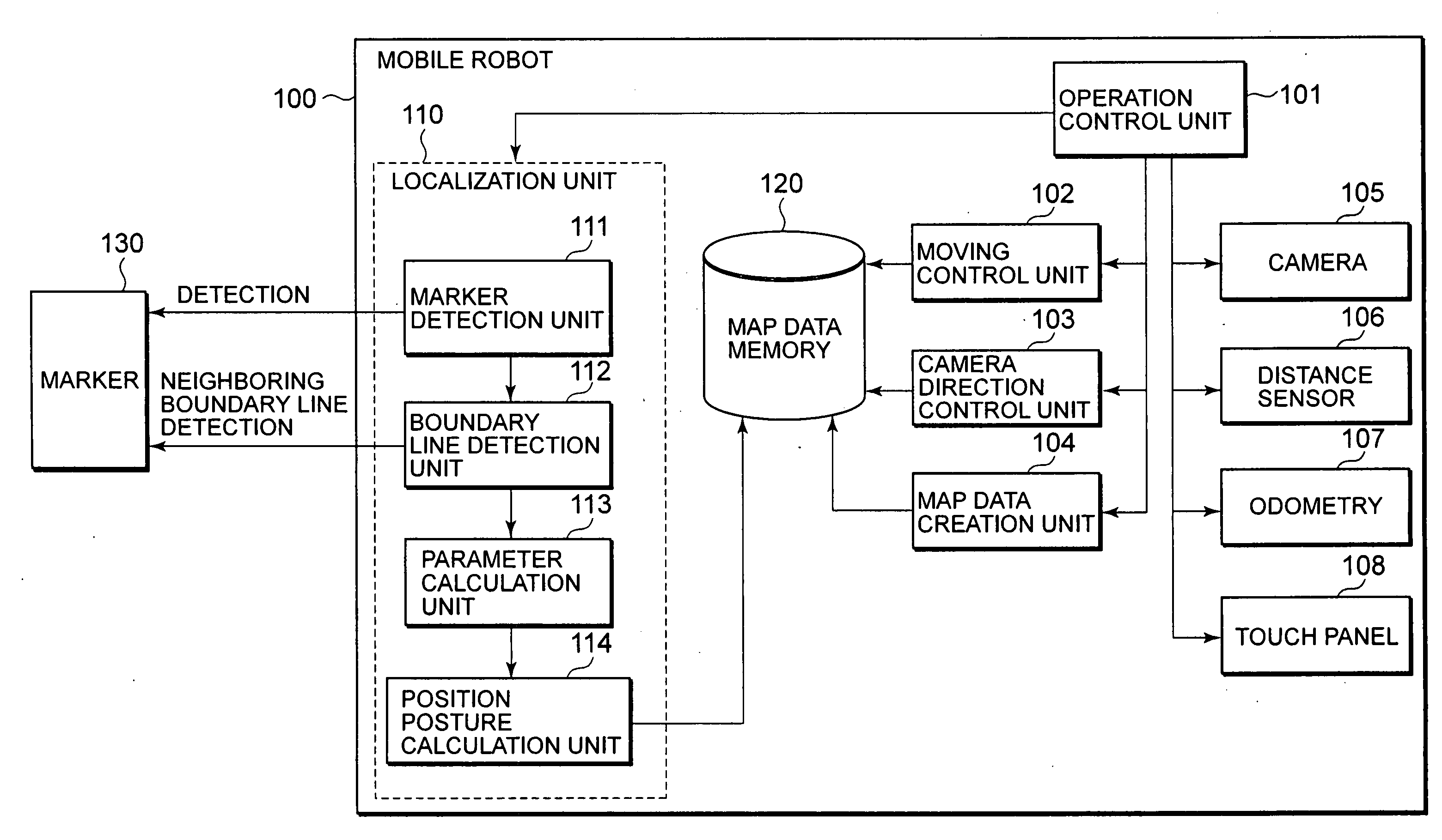
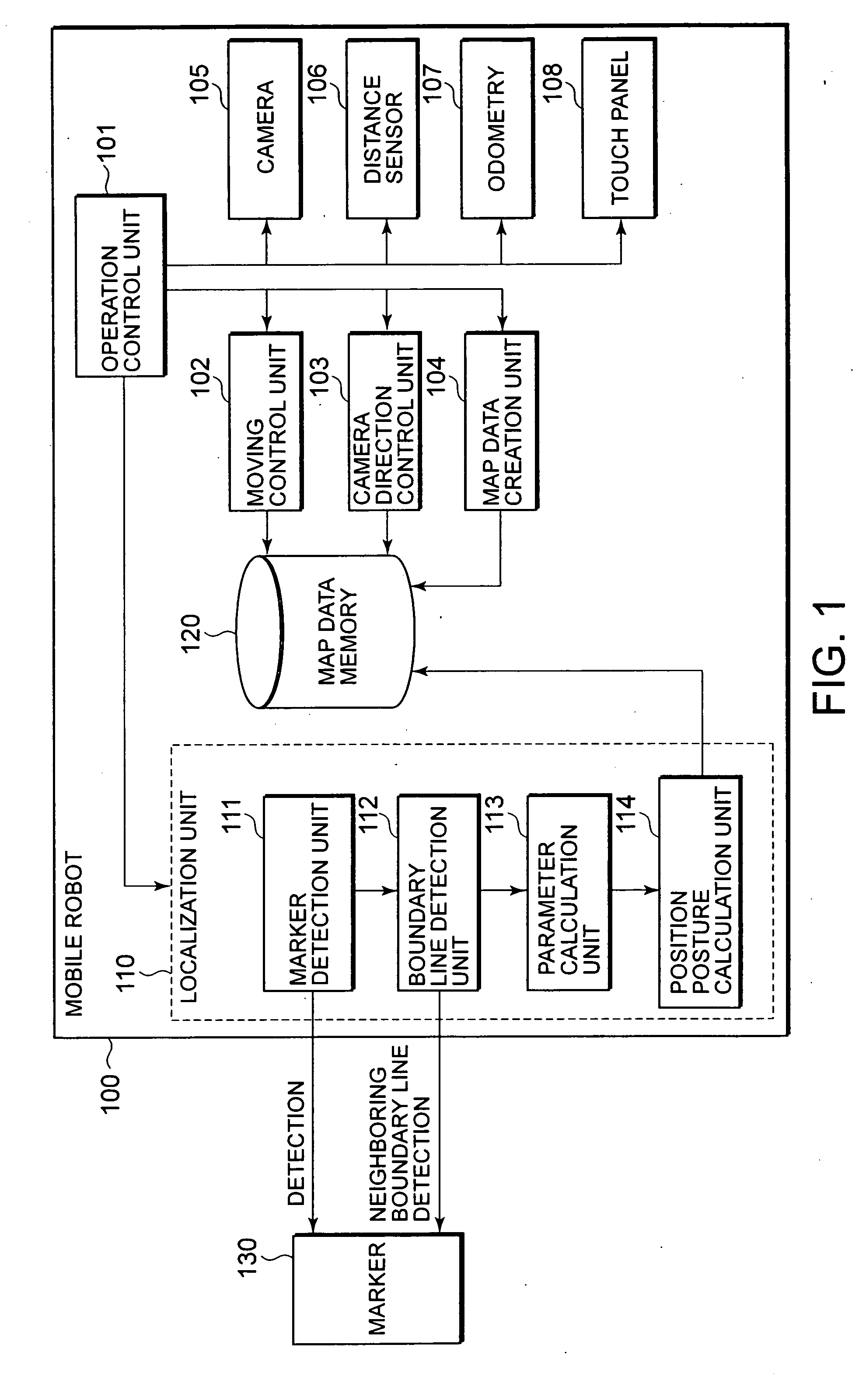
[0029] In embodiments of the present invention, a marker identifiable by a light emission pattern and a boundary line near the marker are detected from an image photographed by a camera. Based on the boundary line and map data (position data of the marker and the boundary line) previously stored in a memory, a position and a posture of an apparatus (mobile robot) is calculated.

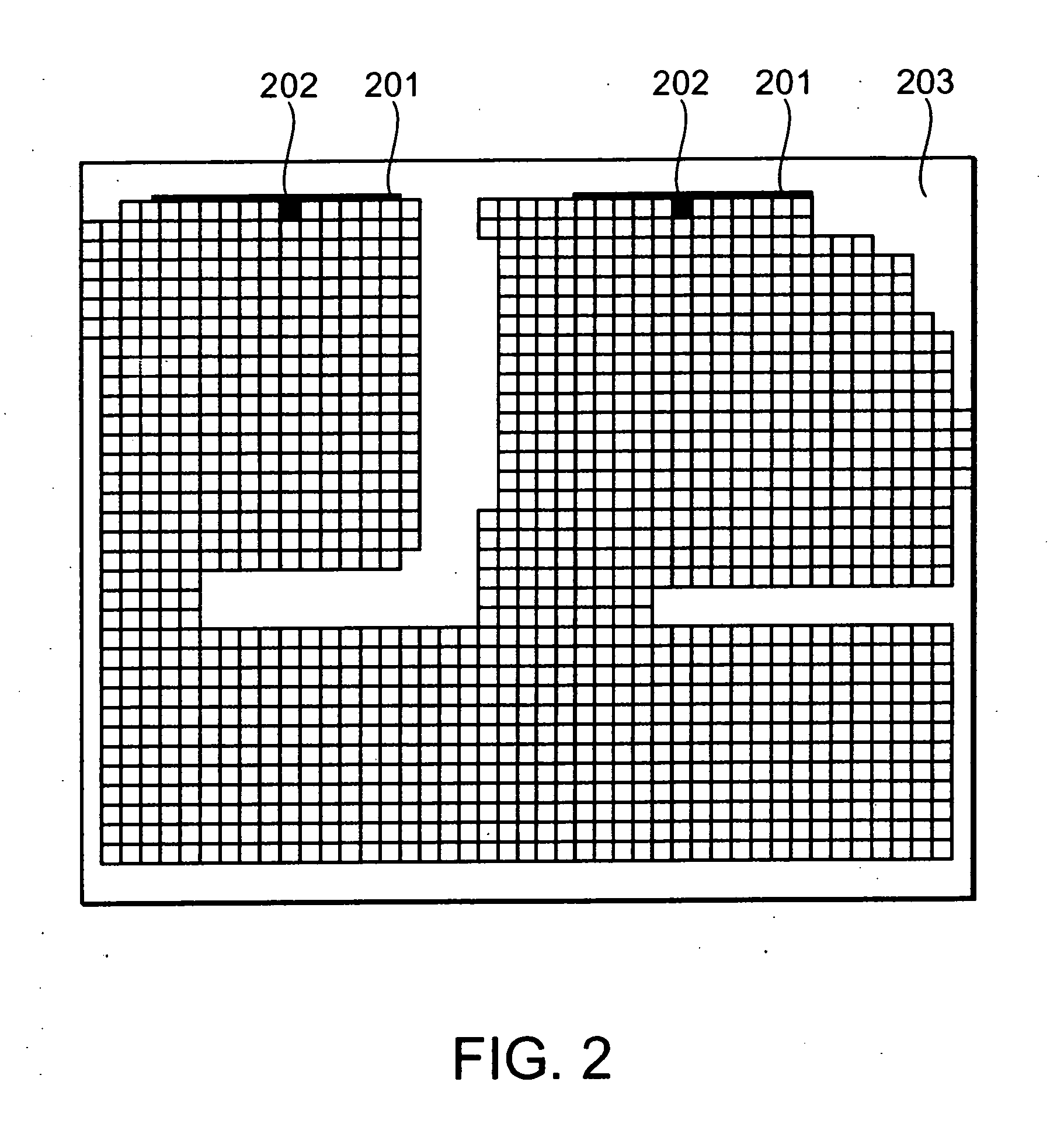
[0030] The marker is a landmark located at a predetermined place in a mobile region allowing a robot to calculate its position and posture. The boundary line is a line near the marker, which divides the inside of the moving region into a plurality of objects (areas).

[0031]FIG. 1 is a block diagram of a mobile robot 100 according to one embodiment of the present invention. In FIG. 1, as a main software component, the mobile robot 10...


PUM


Abstract

A map data memory stores map data of a movement region, position data of a marker at a predetermined place in the movement region, identification data of the marker, and position data of a boundary line near the marker in the movement region. A marker detection unit detects the marker in an image, based on the position data of the marker and the identification data. A boundary line detection unit detects the boundary line near the marker from the image. A parameter calculation unit calculates a parameter of the boundary line in the image. A position posture calculation unit calculates a position and a posture of the mobile robot in the movement region, based on the parameter and the position data of the boundary line.

Description

CROSS-REFERENCE TO RELATED APPLICATIONS [0001] This application is based upon and claims the benefit of priority from prior Japanese Patent Application No.2005-172854, filed on Jun. 13, 2005; the entire contents of which are incorporated herein by reference. FIELD OF THE INVENTION [0002] The present invention relates to a mobile robot and a method for calculating position and posture of a mobile robot autonomously traveling to a destination. BACKGROUND OF THE INVENTION [0003] Recently, a mobile robot which recognizes a surrounding environment and autonomously travels while localizing a self-apparatus and avoiding obstacles is developed. In an autonomous traveling system of such mobile robot, it is important that a position (location) of the self-apparatus (mobile robot) is exactly detected. [0004] As a method for detecting a self-location of the mobile robot, first, a plurality of landmarks are detected from an image photographed by a camera mounted on the mobile robot. Based on the...

Claims


Application Information

Patent Timeline
IPC IPC(8): G05D1/00G01C22/00
CPCG05D1/0234G05D1/0274G05D1/0272G05D1/0255B25J19/02B25J19/04B25J5/007Y10S901/01
Inventor NAKAMOTO, HIDEICHI
Owner KK TOSHIBA
Why Eureka
Try Eureka