Fuel injector nozzle manufacturing method

a manufacturing method and fuel injector technology, applied in the direction of engines, mechanical equipment, machines/engines, etc., can solve the problems increasing the manufacturing difficulty of this part, and therefore more expensive, and achieve the effect of increasing the overall manufacturing cos

Inactive Publication Date: 2007-01-04
BRP US
View PDF13 Cites 8 Cited by
  • Summary
  • Abstract
  • Description
  • Claims
  • Application Information

AI Technical Summary

Benefits of technology

[0013] Although the process shown in FIG. 5 does allow the manufacture of complex fuel injector nozzles, it is a lengthy process requiring multiple steps which increase the overall manufacturing cost.

Problems solved by technology

This results in more complex fuel injector nozzle design and tighter dimensional tolerances which makes the manufacture of this part increasingly difficult, and therefore more expensive.
Although the process shown in FIG. 5 does allow the manufacture of complex fuel injector nozzles, it is a lengthy process requiring multiple steps which increase the overall manufacturing cost.

Method used


Image

  • Fuel injector nozzle manufacturing method
  • Fuel injector nozzle manufacturing method
  • Fuel injector nozzle manufacturing method

Examples


Embodiment Construction

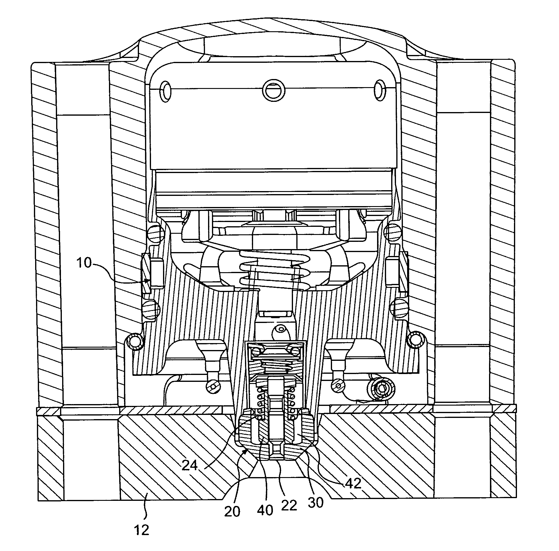
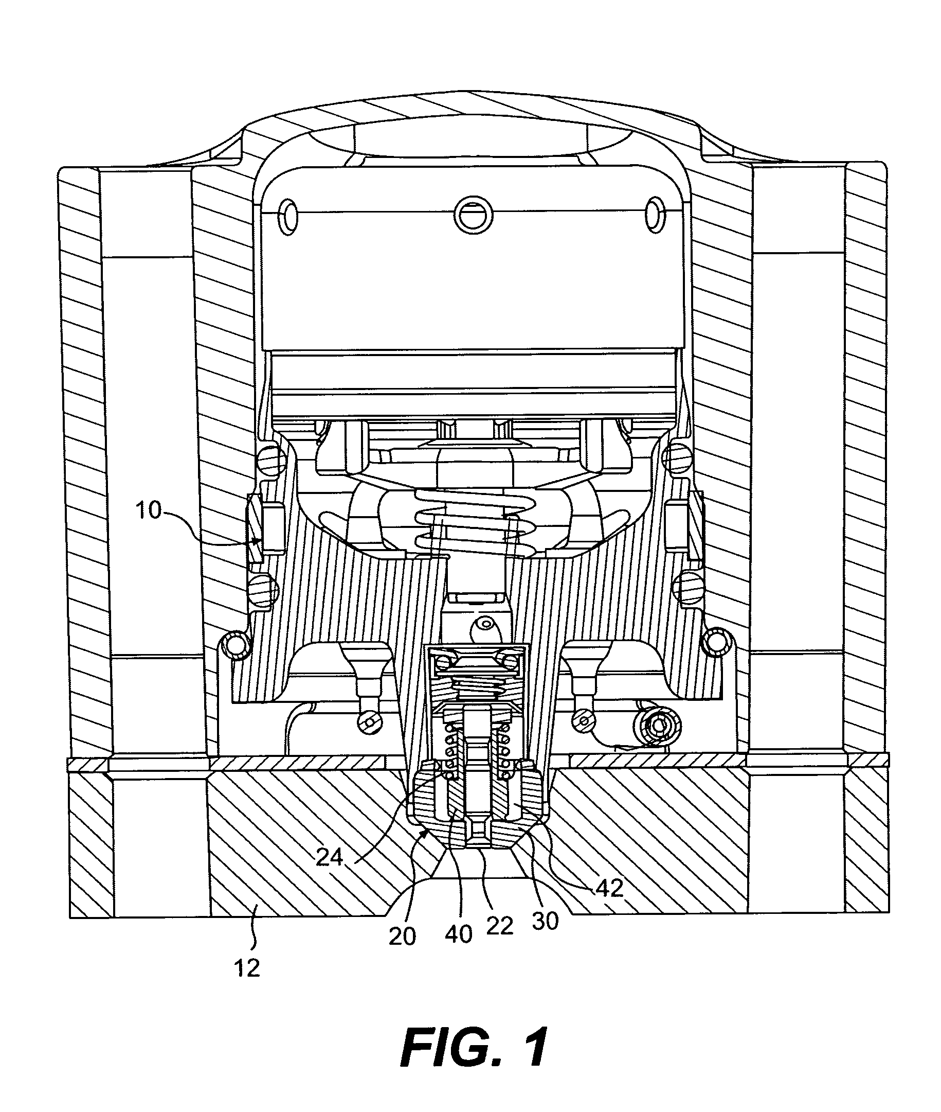
[0041] The invention is described with reference to a fuel injector nozzle. However, it is contemplated that the method described herein can be used with any type of nozzles and assemblies having similar manufacturing requirements as a fuel injector nozzle.

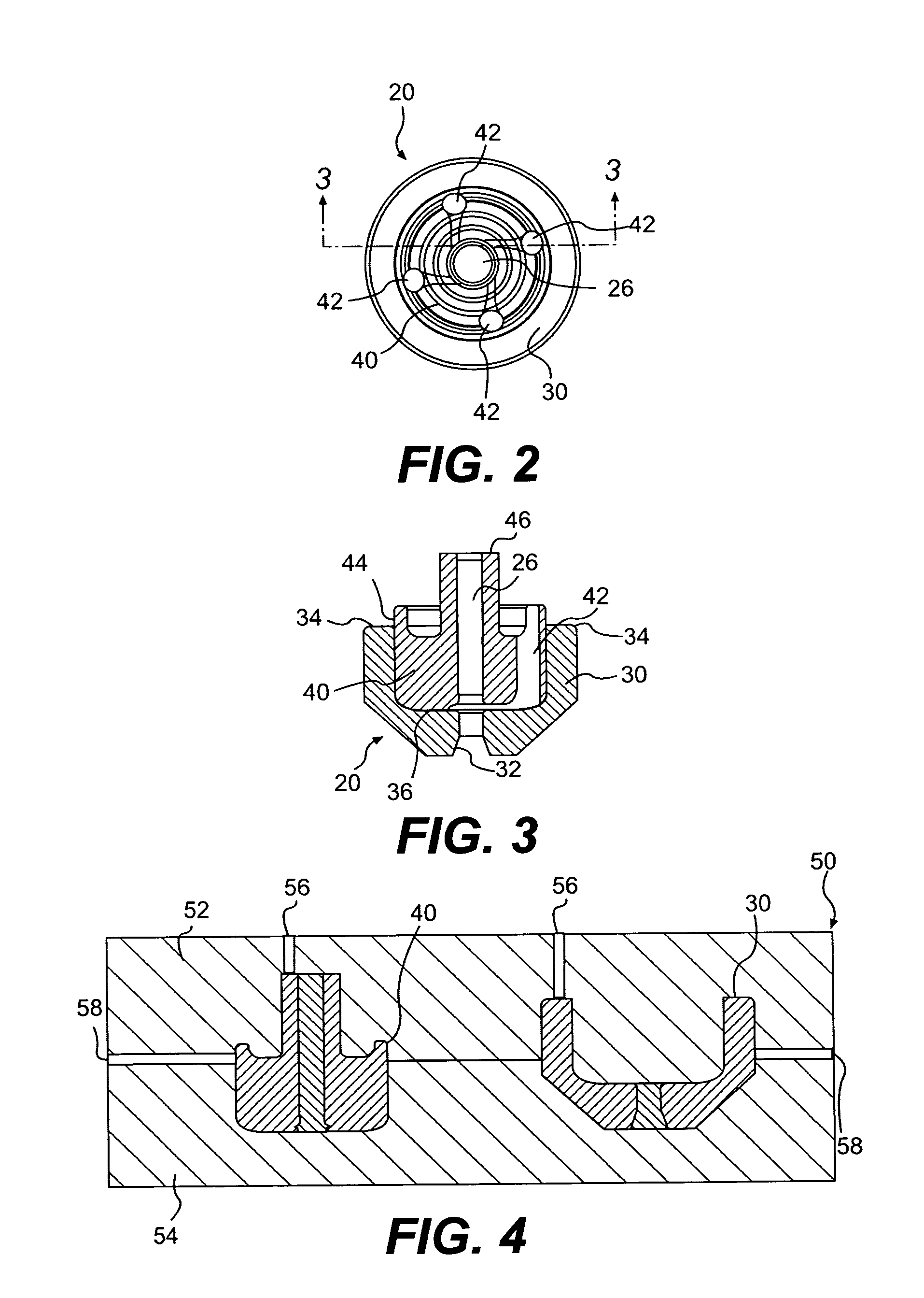
[0042] Referring now to FIG. 6, both the nozzle seat 30 and the nozzle insert 40 are made using MIM. Various MIM materials 210 can be used depending on the desired final material.

[0043] The MIM material 210 is first heated and then injected into molds corresponding to the shapes of the nozzle seat 30 and the nozzle insert 40. In a preferred embodiment, the injection molding steps 215 are done simultaneously using a single mold 50 where the mold cavities for the nozzle seat 30 and the nozzle insert 40 are disposed side by side as seen in FIG. 4. The mold 50 has a top portion 52 and a bottom portion 54. The top portion has injection gates 56 to allow for the MIM material to be injected. Vents 58 are provided between the top portio...


PUM

PropertyMeasurementUnit
combustion characteristicsaaaaaaaaaa
shapeaaaaaaaaaa
sizeaaaaaaaaaa

Abstract

A method of manufacturing a fuel injector nozzle where a nozzle seat and a nozzle insert are made using a metal injection molding process. The nozzle seat and the nozzle insert are assembled and bonded together while in their green state. The resulting nozzle assembly is then debinded and sintered to obtain the desired fuel injector nozzle.

Description

CROSS-REFERENCE [0001] This application claims priority to U.S. Provisional Patent Application 60 / 695,013, filed Jun. 30, 2005, entitled “Fuel Injector Manufacturing Method”, the entirety of which is incorporated herein by reference.FIELD OF THE INVENTION [0002] The present invention relates to a manufacturing method for fuel injector nozzles. The present invention more specifically relates to a manufacturing method for fuel injectors using a metal injection molding process. BACKGROUND OF THE INVENTION [0003] One of the most critical parts of a fuel injector 10, such as the one seen in FIG. 1, is the fuel injector nozzle 20. The nozzle 20 is critical because it is responsible, in part, for the fuel spray characteristic which determines the combustion characteristics of the engine. [0004] As engine emission standards become more stringent, so does the need for improved fuel spray characteristics. This results in more complex fuel injector nozzle design and tighter dimensional toleran...

Claims


Application Information

Patent Timeline
Patent Type & Authority Applications(United States)
IPC IPC(8): B21K3/00B21K1/22
CPCB22F7/062B22F2998/10F02B2275/14F02M61/14F02M61/166F02M61/168F02M61/18F02M61/20F02M2200/8046F02M2200/9053B22F3/225B22F3/1021B22F3/10Y02T10/123Y10T29/49314Y10T29/49231Y10T29/49298Y02T10/12
Inventor CHUNG, KENNETHTOCCI, RAULNEHMER, DANIELTHOMPSON, ROBERT
Owner BRP US
Why Eureka
Try Eureka