
Method and apparatus for handling small quantities of fluids

a technology for handling fluids and small quantities, applied in the direction of measuring devices, sampling, instruments, etc., can solve the problems of significant measurement errors, unresolved pct curves, and internal volume change in the system as a whol

Active Publication Date: 2007-01-04
HY ENERGY
View PDF7 Cites 30 Cited by
  • Summary
  • Abstract
  • Description
  • Claims
  • Application Information

AI Technical Summary

Benefits of technology

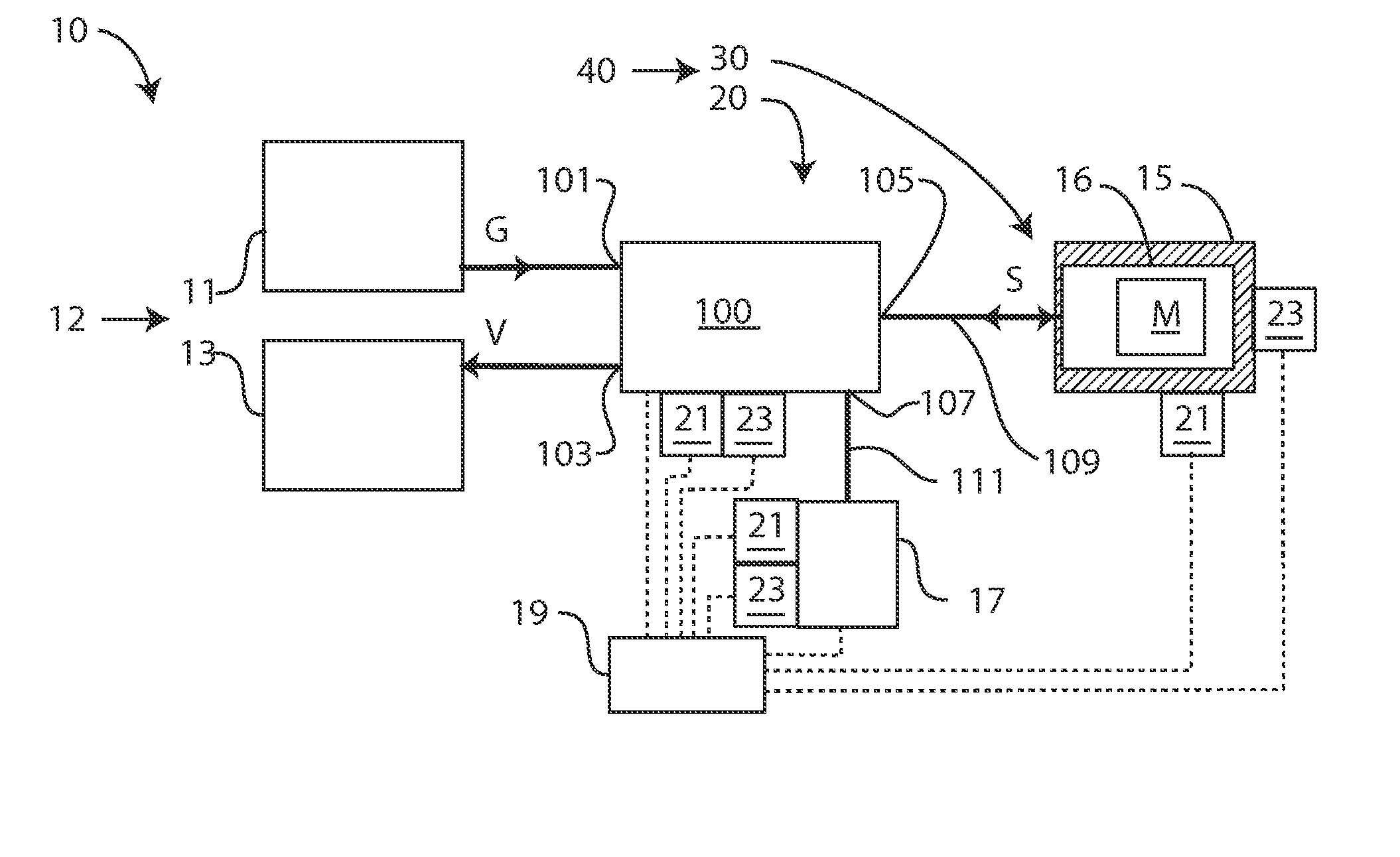
[0019] It is another aspect of the present invention to provide an apparatus having a small dosing volume that can be attached to one of many different types of gas / liquid analyzers, gas / liquid manifolds, and gas sorption / desorption isotherm measuring instruments. In another embodiment, the apparatus performs measurement by applying precise aliquots of gas or liquid using an automatic rotary valve that can dose small quantities of gas or liquid (ca, 0.01 to 500 sml depending on the dosing volume and pressure). In yet another embodiment, the apparatus measures without a system volume change by dosing with a rotary valve, greatly improving the accuracy of gas / liquid uptake and release measurements.
[0022] It is another aspect of the present invention to provide better apparatus for measuring gas or liquid sorption and desorption properties of small samples of materials by dosing the sample with small quantities of gas or liquids.
[0023] It is yet another aspect of the present invention to provide an apparatus that has no change in system volume on filling a reservoir with a gas or a liquid and subsequently dosing the gas or liquid to a sample for sorption or desorption.

Problems solved by technology

One problem with these types of valves is that the diaphragm or stem moves in a lateral motion to open or close the valve, causing an internal volume change in the system as a whole.
Volume changes on the order of 0.05 milliliters, for example, may cause significant measurement error if not taken into account when calculating the mass balance of a gas dosing system.
There are many problems and issues with conventional Sieverts' devices and with other prior art methods and devices for measuring sorption.
This may involve large numbers of repetitive operations, such as delivering aliquots in a PCT measurement, or switching between sorption and desorption in cycle-life measurements.
Without a detailed and even distribution of data points over the entire pressure range, the PCT curve will not be well resolved and certain portions may not be observed at all.
Variations in air temperature in a room in which measurements are performed, or variations in the gas temperature throughout a measurement device, can produce significant errors in measuring the quantity of gases sorption or desorption from a material.
Even if the surrounding air temperature is measured and introduced into the equation of state, the time lag between changes in the temperature of the surrounding air and the temperature of the gases in a Sieverts apparatus can be significant enough that the data can not be sufficiently corrected.
Small samples, such as those of 1 gram or less, and / or samples that adsorb or absorb only small quantities of gas, for example 50 milliliters STP or less, are difficult to investigate using typical volumetric devices that often have calibrated volumes and piping with volumes on the order of 10 milliliters or more.
However, to be able to measure gas sorption on very small samples using the Sieverts method, very small dosing volumes are required.
Manual orifice-and-seat-type valves found in prior art devices are subject to inconsistent operator behavior.
In particular, operators have a tendency to over-tighten valves during high-pressure experiments, resulting in valve seat damage causing the valve to leak.
Manual systems have been known to operate for only a few experiments before the valves leak to the point that the data is seriously compromised.

Method used


Image

  • Method and apparatus for handling small quantities of fluids
  • Method and apparatus for handling small quantities of fluids
  • Method and apparatus for handling small quantities of fluids

Examples


first embodiment

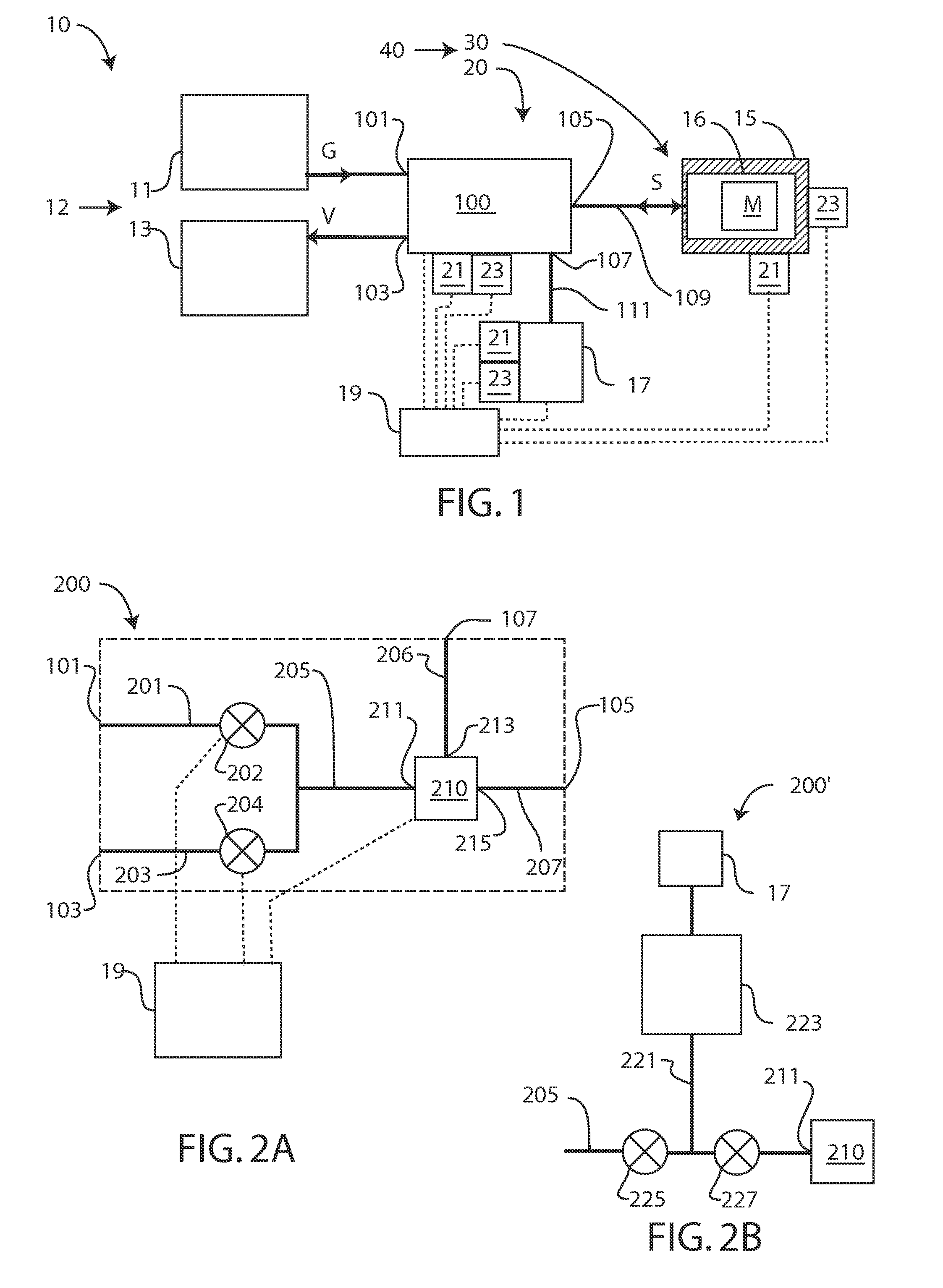
[0077]FIG. 2A is a schematic diagram of a first embodiment valve system 200 of the present invention which may be generally similar to valve system 100, except as further detailed below. Where possible, similar elements are identified with identical reference numerals.

[0078] Valve system 200 includes a first valve 202, a second valve 204, a third valve 210, having a first port 211, a second port 213, and a third port 215, each under the control of computer system 19, and passageways 201, 203, 205, 206, and 207. Passageway 201 connects port 101 and first valve 202, passageway 203 connects port 103 and second valve 202, passageway 205 connects the first and second valves to first port 211, passageway 206 connects second port 213 to port 107, and passageway 207 connects third port 215 to port 105.

[0079] First valve 202 and second valve 204 are on / off valves that are electrically controlled by computer system 19 to control fluid communication between ports 101 and 103, respectively, an...

second embodiment

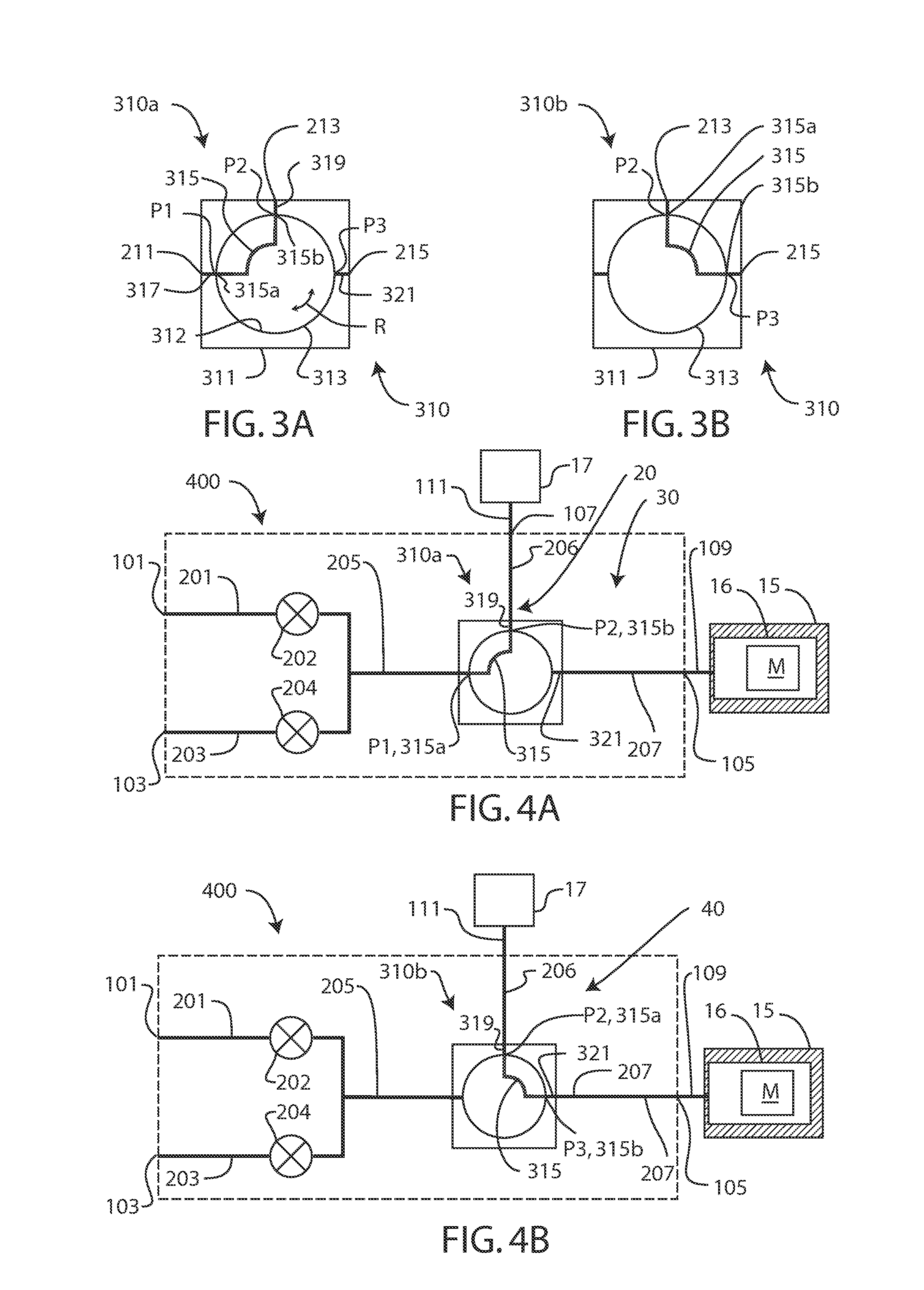
[0094] In one embodiment, valve 510 is a rotary valve. FIGS. 6A and 6B are schematic diagrams of a rotary valve 610 suitable for use as valve 510, where FIG. 6A shows rotary valve 610 in a first position 610a, and FIG. 6B shows rotary valve 610 in a second position 610b. Rotary valve 610 may be generally similar to valves 210, 310, or 510, except as further detailed below. Where possible, similar elements are identified with identical reference numerals.

[0095] Rotary valve 610 has a housing 611, which is generally similar to housing 311, except that it does not have a passageway 319. Rotary valve 610 is a two-port, two-position valve, where FIG. 6A shows the rotary valve in a first position 610a and FIG. 6B shows the rotary valve in a second position 610b. The use of rotary valve 610 for valve 510 can result in a lower dosing volume, since the port for measuring pressure (such as port 213 of FIG. 2) is eliminated, further reducing the volume of dosing reservoir 20 to the volume of p...

third embodiment

[0100]FIG. 9 is a schematic diagram of a dosing / bypass valve system 900 of the present invention which may be generally similar to valve systems 100, 200, 400, 500, 700, or 800 except as further detailed. Where possible, similar elements are identified with identical reference numerals.

[0101] Dosing / bypass valve system 900 includes a valve 910 having at least four ports and three positions. More specifically, valve 910 has first, second, and third ports 211, 213, and 215, respectively, and a fourth port 903, and a passageway 901 that connects passageway 207 to port 903. Valve 910, which may be generally similar to valve 210, 510, or 810 except as noted subsequently, includes a third position that connects ports 903 and 211. As with valve 210, and 810, valve 910 has a first position that connects that connects ports 211 and 213, a second position that connects ports 213 and 215. The third position that connects ports 903 and 211 and which is useful, in measurement apparatus 10, in pr...


PUM

PropertyMeasurementUnit
volumeaaaaaaaaaa
volumeaaaaaaaaaa
volumeaaaaaaaaaa

Abstract

The invention relates to a method and an apparatus for handling small quantities of fluids useful, for example, in measuring the gas and / or liquid sorption and desorption properties of substances such as hydrogen sorption by solid or liquid hydrogen storage materials. In one embodiment, low-volume rotary valves are used to dose samples in a sample holder. In another embodiment, a rotary valve is used as a dosing / bypass valve to both condition and measure samples. The invention also relates to an actuator for a rotary valve that has a manual override feature.

Description

RELATED APPLICATIONS [0001] This application claims the benefit under 35 U.S.C. § 119(e) of: U.S. Provisional Application No. 60 / 692,344, filed Jun. 20, 2005, titled METHOD AND APPARATUS FOR MEASURING SMALL QUANTITIES OF GAS OR LIQUID SORPTION AND DESORPTION PROPERTIES OF MATERIALS; and U.S. Provisional Application No. 60 / 803,655, filed Jun. 1, 2006, titled METHOD AND APPARATUS FOR HANDLING SMALL QUANTITIES OF GASES OR LIQUIDS. The entire contents of the above-listed provisional applications are hereby incorporated by reference herein and made part of this specification.BACKGROUND [0002] 1. Field of the Invention [0003] The present invention relates to handling devices for fluids, including but not limited to gases or liquids, and specifically to the control of small quantities of fluids and to devices for performing measurements on small quantities of gases or liquids. [0004] 2. Description of the Background [0005] One common way to determine gas sorption properties of a material i...

Claims


Application Information

Patent Timeline
Patent Type & Authority Applications(United States)
IPC IPC(8): G01N1/14
CPCG01N7/04G01N2015/0873G01N7/14
Inventor GROSS, KARL
Owner HY ENERGY
Learn More