

Continuous glass filaments manufacturing equipment
a technology of continuous glass filaments and manufacturing equipment, which is applied in the direction of manufacturing tools, furniture, lighting and heating equipment, etc., can solve the problems of reducing production yield, uneven temperature profile of bushing 1, and deterioration, so as to avoid complex design, enhance cooling effect, and excellent cooling
Inactive Publication Date: 2003-06-12
OCV INTELLECTUAL CAPITAL LLC
View PDF15 Cites 2 Cited by
- Summary
- Abstract
- Description
- Claims
- Application Information
AI Technical Summary
Benefits of technology
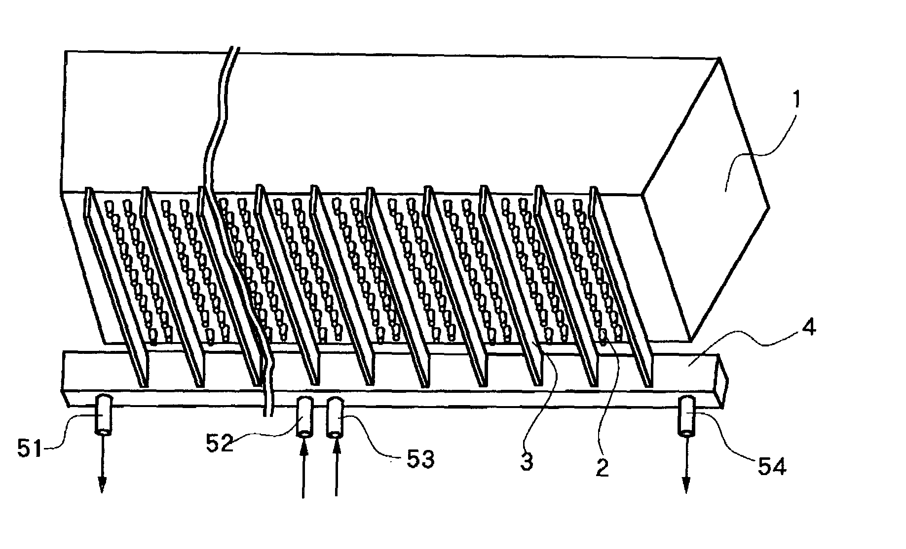
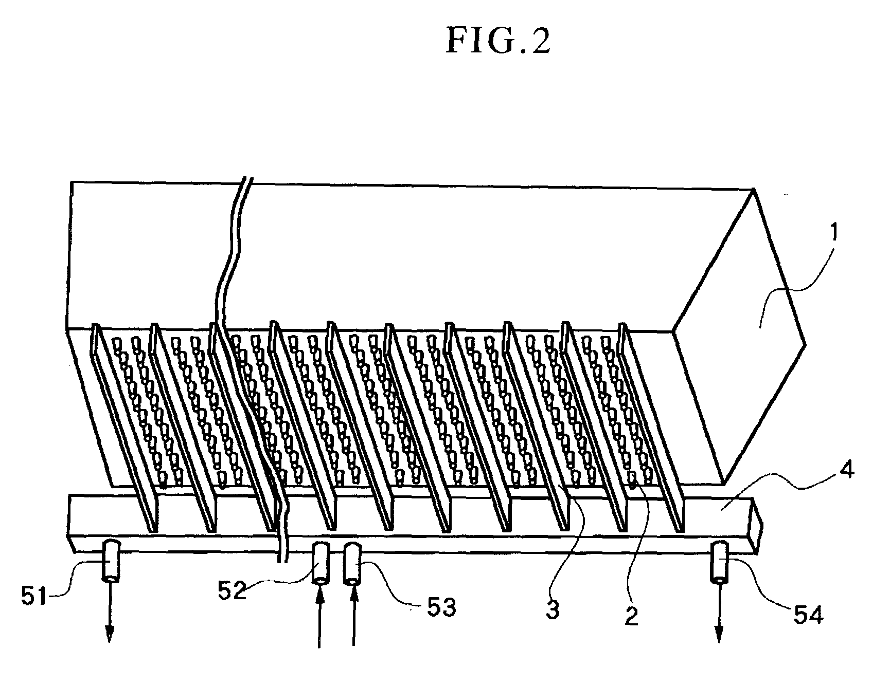
[0025] Owing to the arrangement of coolant inlet / outlet ports at at least three locations in total per each manifold 4 as described above, the present invention can bring about the above-described advantageous effects. Embodiments each equipped with a coolant inlet port practically at one location of the manifold 4 and outlet ports at two or more locations, respectively, of the manifold 4, specifically the constructions shown in FIGS. 2 and 3, FIG. 4A and FIG. 4B are preferred, because the flow of coolant through the manifold 4 becomes uniform and the fins 3 can be efficiently cooled. More preferred embodiments are those each equipped with coolant inlet ports at two or more locations, respectively, of the manifold 4 and a coolant outlet port practically at one location of the manifold 4, specifically the embodiment of FIG. 4C.
[0026] Reference is next had to FIG. 5 to describe the still further embodiment of the present invention. FIG. 5 is a view of a bushing 1, manifolds 4 and fins as seen from a lower point. Support bars 8, 8 are arranged on a lower part of the bushing 1 to prevent the formation of molten glass into filaments from becoming unstable due to flexion of the bushing 4 under the weight of the molten glass. As the support bars 8, 8 are arranged, rows of nozzles (not shown) arranged on the bushing 1 are divided into 4 blocks. Each block is provided with its own manifold 4, and fins 3 joined to the manifold 4 are arranged in all second ones of spaces between the rows of associated nozzles. In the continuous glass filament production apparatus according to the yet further embodiment as illustrated in FIG. 6, each two adjacent blocks located side by side are provided with a single continuous manifold 4. Needless to say, the coolant inlet / outlet ports 51-54 arranged on the manifolds 4 in FIGS. 5 and 6 can be arranged in various combinations as illustrated in FIGS. 4A through 4D without being limited to the combinations illustrated in FIGS. 5 and 6.
[0027] In each apparatus according to the present invention, each manifold is required to cool its associated fins by introducing coolant through one or more inlet ports, allowing the coolant to pass through the hollow section of the manifold, and then discharging the coolant through one or more outlet ports, with the proviso that the total number of the inlet and outlet ports is three or more. In the present invention, no particular limitation is imposed on the arrangement of the manifolds. It is, however, preferred to arrange them along at least one side of a bushing by which molten glass is formed into filaments. Arrangement of manifolds along a longer side of a bushing makes it possible to bring the length of fins into conformity with the length of the bushing in the direction of its shorter side, so that the fins can be formed shorter to bring about an excellent cooling effect. It is, therefore, more preferred to arrange manifolds along a longer side of a bushing. Adoption of such a construction can avoid a complex design, and is preferred from the standpoint of cost.
[0028] As the material for the manifold(s), use of copper, silver or the like is preferred because the manifold(s) can be protected from deteriorations due to heat from the bushing and the cooling effect can be enhanced.
[0029] Examples of the coolant can include water, alcohol, ammonia, and liquefied nitrogen. Two or more of these coolants may be also used in combination. As use of water is generally preferred from the standpoint of cost, the coolant will hereinafter be called "cooling water". No particular limitation is imposed on the temperature of cooling water, but the temperature of cooling water may range preferably from 10 to 30.degree. C., more preferably from 15 to 20.degree. C.
[0030] No particular limitation is imposed on the flow rate of the cooling water through each manifold. In view of the size and weight of each manifold attached to a bushing, however, a flow rate of from 3.0 to 20 L / min is preferred. Since water is not caused to flow continuously in one direction, the present invention makes it possible to allow cooling water to flow at a flow rate about twice as much as the flow rate at which cooling water was caused to flow in one direction through a manifold of conventional size. It is, therefore, possible to cause cooling water to flow at a large flow rate of from 6.0 to 20 L / min. As a consequence, the manifold and fins can be cooled efficiently and fully.
Problems solved by technology
Due to this temperature difference and other causes, the fins 3 joined to the manifold 4 tend to become uneven in temperature and hence, are accompanied by problems such that the fins may undergo deteriorations by separation of an anti-corrosive plating applied to the fins 3 and the fins 3 may become uneven in cooling capacity to make the temperature profile of the bushing 1 uneven.
(1) By increasing the flow rate of coolant to have more heat absorbed by the fins 3, the temperature difference between the inlet port 9 and the outlet port 10 can be decreased. There is, however, a limitation to the flow rate of coolant which can be allowed to flow in a direction so that deteriorations of the fin 3 still cannot be avoided. Accordingly, the temperature profile of the bushing 1 becomes uneven, and the resulting glass filaments involve problems such that they vary in diameter, are prone to breakage, and may be lowered in production yield. To increase the flow rate of coolant in a direction, it is necessary to increase the diameter of the hollow section of the manifold 4. This naturally necessitates to make the manifold 4 bigger, leading to problems that a higher material cost is required and the convenience of assembly such as attachment is lowered.
(2) By lowering the temperature of coolant, a relatively efficient cooling effect can be obtained because the temperature of the coolant remains low throughout the hollow section of the manifold 4, although a temperature difference still occurs between the inlet port 9 and the outlet port 10. This measure, however, requires a cooling apparatus, and is accompanied by problems that a higher initial cost is required and more complex production facilities are needed.
(3) By increasing the thickness of the fins 3, the progress of their corrosion can be retarded. This measure, however, involves a problem that the machinability of the fins, such as angle adjustability of the fins 3 in a gathering direction of filaments, is reduced.
(4) By decreasing the length of the fins 3, the progress of their corrosion can also be retarded. Heat absorption, however, is proportional with the length of the fins 3, so that the number of nozzles 2 which can be arranged must be determined depending upon the length of the fins 3. Therefore, use of shorter fins leads to a need for decreasing the number of nozzles 2, and is not preferred.
(5) If the manifold 4 is divided to provide the bushing 1 with many manifolds 4, a relatively efficient cooling effect can be brought about. This measure, however, involves problems that a higher initial cost is required and more complex production facilities are needed. Further, use of many manifolds 4 requires to leave spaces between individual manifold-fins units. This, however, naturally requires a reduction in the number of nozzles, leading to a problem that the efficiency of production of glass filaments is lowered.
Method used
View moreImage
Smart ImageViewing Examples

Examples
examples
[0045] The present invention will next be described more specifically based on Examples and Comparative Examples.
Login to View More PUM
| Property | Measurement | Unit |
|---|---|---|
| total flow rate | aaaaa | aaaaa |
| thickness | aaaaa | aaaaa |
| length | aaaaa | aaaaa |
Abstract
An apparatus is provided for producing continuous glass filaments by spinning molten glass through nozzles of a bushing and cooling the thus-spun filaments with fins joined to one or more cooled manifolds and arranged in a proximity of the nozzles. Each manifold is provided at at least three locations thereof with at least one inlet port and at least one outlet port for coolant, respectively, with a proviso that the total number of the inlet and outlet ports is the same as the number of the locations of the manifold. Without using a complex construction, this invention makes it possible to provide the fins with improved durability and to produce the glass filaments with improved quality. In particular, the present invention can be applied to large bushings each of which is equipped with a number of nozzles.
Description
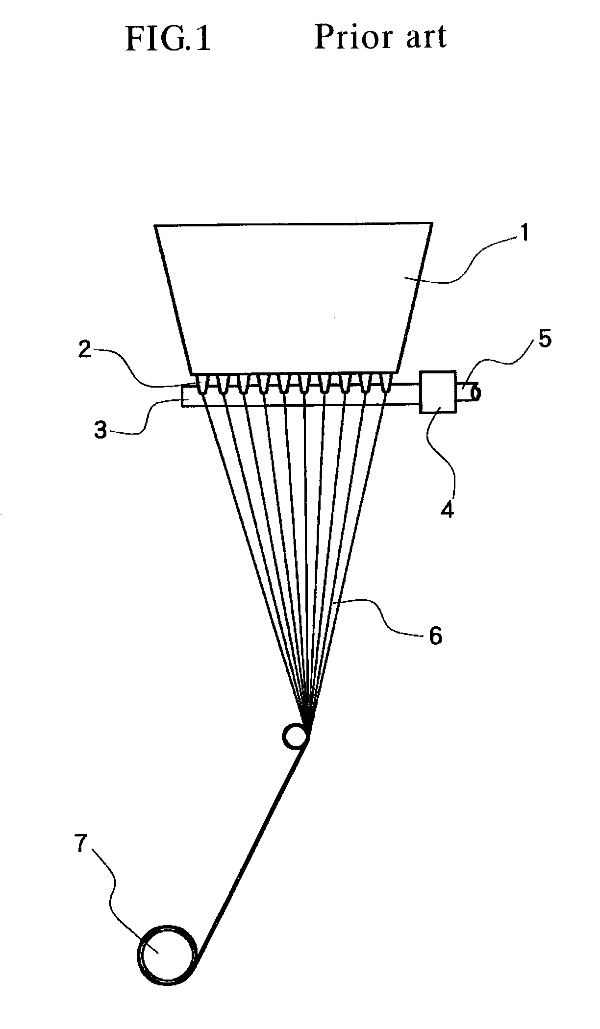
[0001] This invention relates to an apparatus for producing continuous glass filaments by cooling filaments of molten glass while drawing them out of individual nozzles of a bushing.DESCRIPTION OF THE BACKGROUND[0002] As illustrated in FIG. 1, a process has long been used to produce glass filaments 6 by introducing molten glass into a bushing 1, drawing the molten glass through numerous nozzles 2 arranged on the bushing 1, cooling the resulting filaments of the molten glass, and then gathering and taking up the thus-formed glass filaments on a winding roll 7.[0003] As a method for effecting the cooling, it is known to arrange cooled fins 3 in the proximity of the numerous nozzles 2 arranged on the bushing 1 such that the filaments of the high-temperature molten glass are solidified shortly after their melt-spinning through the nozzles 2. As shown in FIG. 7, for example, JP-B-06053591 discloses a method that coolant is introduced through an inlet port of a header (manifold) 4, is cau...
Claims
Login to View More Application Information
Patent Timeline
 Patent Type & AuthorityApplications(United States)
IPC IPC(8): C03B37/12C03B37/02
CPCC03B37/0209Y02P40/57
InventorNISHIMURA, AKIHIRO
OwnerOCV INTELLECTUAL CAPITAL LLC