Thrust fork

a technology of thrust forks and forks, which is applied in the field of thrust forks, can solve the problems of reducing the efficiency of conventional thrust forks in a place, causing a lot of trouble, and reducing the production cost, so as to reduce production costs and facilitate arrest. , the effect of simplifying the structur

Inactive Publication Date: 2007-01-04
PORTA IND
View PDF18 Cites 14 Cited by
  • Summary
  • Abstract
  • Description
  • Claims
  • Application Information

AI Technical Summary

Benefits of technology

[0007] The present invention is made by taking the matters mentioned above into consideration, and an object of the present invention is to provide a thrust fork in which a structure can be made simple by making good use of the advantage of the prior art and adding an improvement, the work for resetting the opening and closing rods in the prior art can be omitted, and a criminal or the like can be constrained without having the danger of being stabbed by the edge tool even in the case of arresting the criminal holding the edge tool, so as to easily arrest the criminal.
[0015] When the leading ends of the thrust fork main body are pressed to the thigh or the like of the criminal or the like at a time of arresting the criminal or the like, both the opening and closing rods swivel in the direction of moving apart from each other so as to open the leading ends of the forked rod and introduce the thigh or the like into the inner side of the forked rod. Further, after the thigh or the like has passed the portion between the leading ends of both the opening and closing rods, both the opening and closing rods are returned on the basis of the operation of the returning means, and the leading ends of the forked rod are closed, so that, the thigh or the like becomes in the state of entering into the forked rod. Accordingly, since the thigh or the like of the criminal or the like is constrained, and the motion thereof is regulated, it is possible to arrest the criminal or the like. Further, since the criminal or the like can be tripped sideways by operating the handle portion such as pulling the handle portion in the state of the thigh or the like being caught in the forked rod as mentioned above, it is possible to easily arrest the criminal or the like.
[0022] When the leading ends of the thrust fork main body are pressed to the arm holding the edge tool at a time of arresting the criminal or the like, for example, holding the edge tool, both the opening and closing rods swivel in the direction of moving apart from each other so as to open the leading ends of the forked rod and introduce the arm into the inner side of the forked rod. Further, after the arm has passed the portion between the leading ends of both the opening and closing rods, both the opening and closing rods are returned on the basis of the operation of the returning means, and the leading ends of the forked rod are closed, so that the arm becomes in the state of entering into the ring of the rope. Accordingly, since the arm holding the edge tool is constrained, and the motion thereof is regulated, it is possible to avoid the danger of being stabbed by the edge tool so as to easily arrest the criminal person or the like. Further, in the case that an ankle region of the criminal or the like is pressed by the leading ends of the thrust fork main body, the ankle region is constrained in the state of the angle region being caught in the ring of the rope in accordance with the same operation as mentioned above, and the motion is regulated. Accordingly, since the criminal or the like can be easily tripped sideways by operating the handle portion such as pulling the handle portion or the like, it is possible to easily arrest the criminal person or the like, similarly to the foregoing.
[0025] In accordance with the present invention, the following effects can be obtained. (1) It is possible to simplify the structure so as to reduce a production cost in comparison with the prior art. (2) It is possible to omit the work for resetting both the opening and closing rods. (3) It is possible to constrain the criminal or the like so as to easily arrest. (4) Particularly, in accordance with the second aspect, it is possible to avoid the danger of being stabbed by the edge tool even in the case of arresting the criminal or the like holding the edge tool, and arrest the criminal or the like.

Problems solved by technology

However, the conventional thrust fork has the following problems.
(1) Since the conventional thrust fork is structured such as to press the body of the criminal or the like so as to seize it, the conventional thrust fork can not be effectively used in a place where a wall or a boarding of a building, or a barrier material such as a fence or the like does not exist.
(2) Since a motion of the criminal or the like cannot be held at a position which is apart from the barrier material, there is a risk that that the criminal or the like escapes at a time of arresting.
Accordingly, a lot of trouble is caused in the next action, that is, an arresting operation such as handcuffing or the like.
(4) Since arms can be moved freely, for example, at a time of seizing the criminal or the like who holds an edge tool such as knife or the like, there is a danger that the arresting person is stabbed by the edge tool at a time of arresting by handcuffing or the like.
Further, since the structure, for example, of the lock means or the like is complex, the manufacturing requires a lot of man-hours, and a production cost is increased.

Method used


Image

  • Thrust fork
  • Thrust fork
  • Thrust fork

Examples


embodiment 1

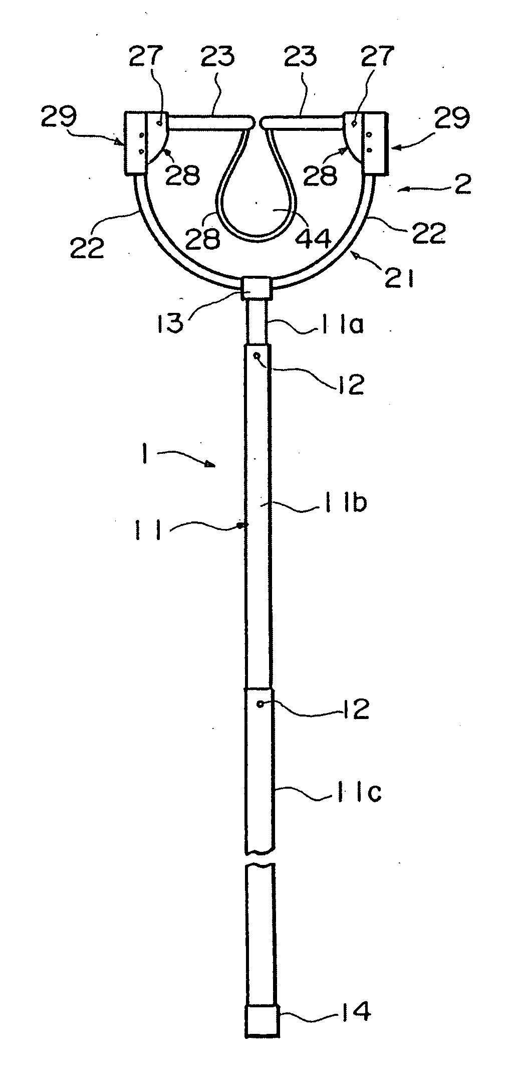
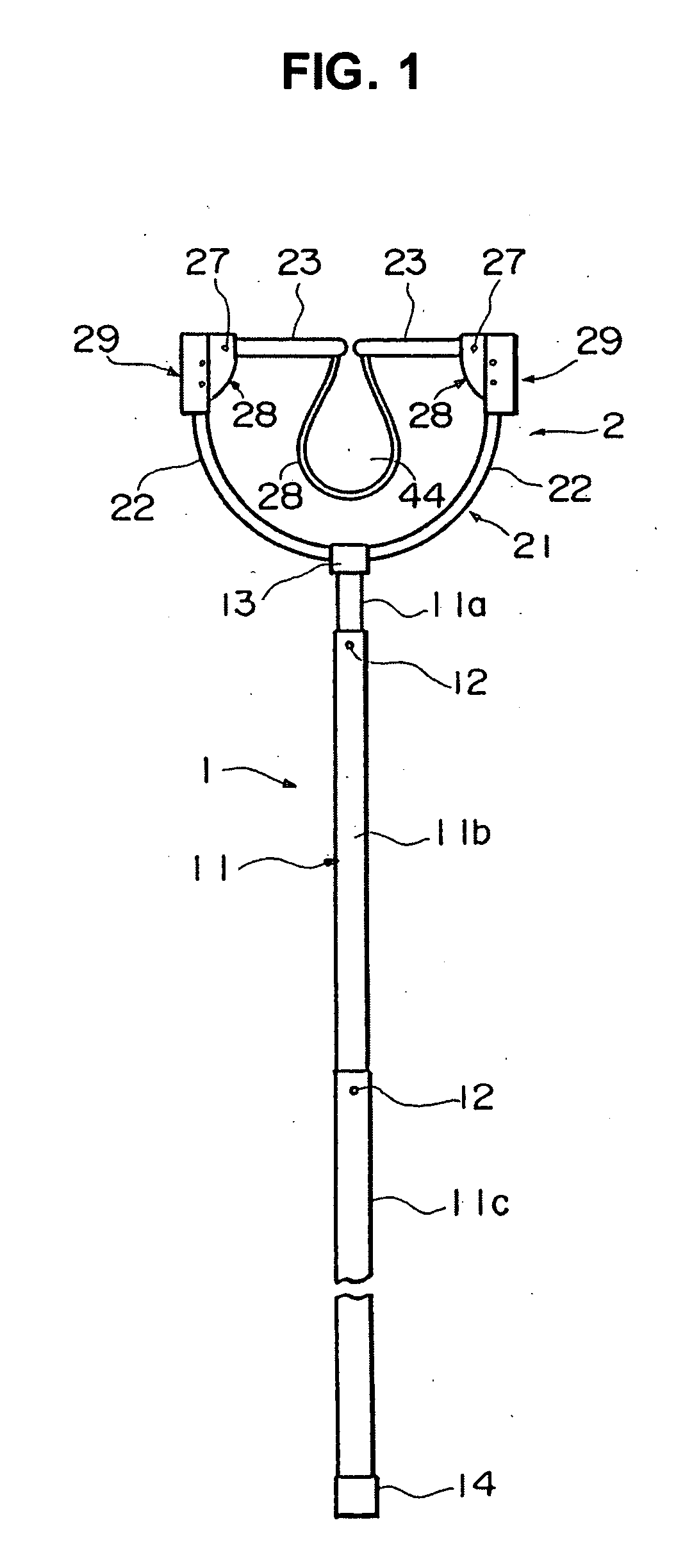
[0039] In FIGS. 1 to 7, the thrust fork in accordance with the embodiment (an embodiment 1) is constituted by a handle portion 1, and a thrust fork main body 2 attached to a leading end portion of the handle portion 1.

[0040] The handle portion 1 is formed in suitable diameter and length optionally. The handle portion 1 in accordance with the embodiment 1 is constituted by a multistage type telescopic rod 11 by fitting an optional number of tubes 11a, 11b and 11c made of an aluminum metal, a plastic or another raw material. The illustrated telescopic rod 11 is structured such as to be expanded and contracted in three stages by using three tubes 11a, 11b and 11c, however, the number of the tubes 11a, 11b and 11c can be optionally increased and reduced.

[0041] The tubes 11a, 11b and 11c have a click button 12 and a button engagement hole (not shown) in a predetermined portion, and is structured such that the button 12 is engaged with the engagement hole at a time of the maximum expansi...

embodiment 3

[0065] The stopper means in accordance with the embodiment 3 is structured by the stopper plate 53 provided in the attaching member 51 as mentioned above.

[0066] The returning means 24 in accordance with the embodiment 3 is structured by a leaf spring 50 having suitable width and length and made of a metal. The leaf spring 50 in accordance with the embodiment 3 is obtained by forming a curved spring portion 50a curved in an approximately circular shape at an approximately center portion of the spring member, and forming a pair of spring pieces 50b and 50c having a suitable length so as to extend from the spring portion 50a.

[0067] Further, the structure is made such that the curved spring portion 50a is arranged so as to be positioned between the base end portion of the opening and closing rod 23 and the upper end surface of the branch rod 22, and pressing force is applied in such a manner that the one spring member 50b is brought into contact with an inner surface (a lower surface i...

embodiment 4

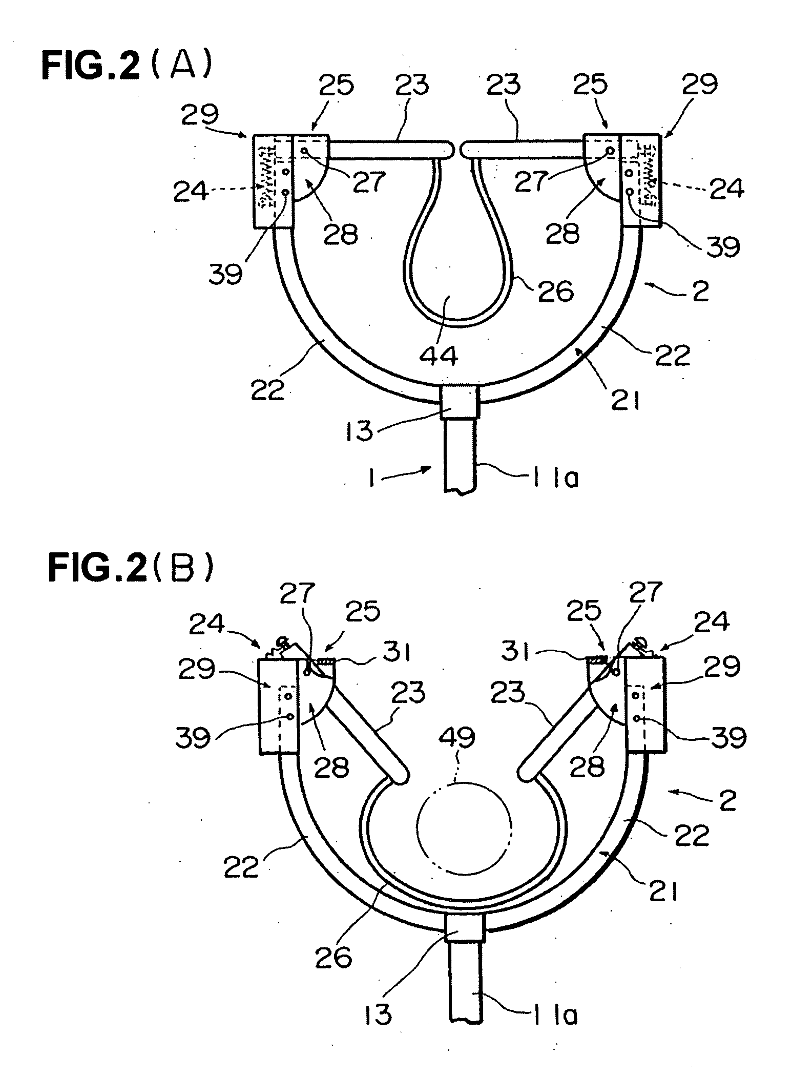
[0072] The thrust fork in accordance with the embodiment 4 is structured as mentioned above. Next, a description will be given of an example of a using method, an operation and the like. For example, in the case of pressing the leading end of the thrust fork main body 2 to the target region 60 (a thigh or the like) of the criminal or the like to hold it between both the branch rods 22 at a time of arresting the criminal or the like, both the opening and closing rods 23 swivel in the direction of moving apart from each other so as to open the leading ends of the forked rod 21 and introduce the thigh or the like 60 into the inner portion side of the forked rod 21. Further, since both the opening and closing rods are returned on the basis of the spring operation of the returning means 24 and the leading ends of the forked rod 21 are closed when the thigh or the like 60 passes through the portion between the leading ends of both the opening and closing rods, the thigh or the like 60 bec...


PUM


Abstract

To provide a thrust fork to arrest a resisting criminal without danger of being stabbed by an edge tool, a thrust fork main body (2) attached to an end of a handle portion (1) is provided with a forked rod (21), movable opening and closing rods (23), which have base end portions respectively pivoted to leading ends of the forked rod and freely swivel only inside the forked rod without outward movement, a returning means (24) to return the opening and closing rods (23) by a spring to an original position, and a constraining rope (26), both ends of which are engaged with leading ends of the opening and closing rods (23) respectively to form a ring 44 having a suitable size inside the forked rod, whereby the end of the forked rod is opened and closed via swiveling of the opening and closing rods.

Description

TECHNICAL FIELD [0001] The present invention relates to a thrust fork used at a time when mainly a police man or the like seizes a criminal, a thug or others to be seized. BACKGROUND ART [0002] As a conventional thrust fork, as shown in FIG. 12 for example, there has been generally known a structure in which a thrust fork main body 103 constituted by a forked rod 104 branched in a semicircular shape, a U shape, a V shape or the like (the semicircular shape in the drawing) is attached to a leading end of a handle portion 101 constituted by a telescopic rod 102 or the like (refer to Japanese Unexamined Patent. Publication No. 7-103695, Japanese Utility Model No. 3089372, Japanese Utility Model No. 3041513, Japanese Utility Model No. 3083227, for example). The thrust fork is structured such that the police man or the like holds the handle portion 101 by hands and presses a body of a criminal or the like by the forked rod 104 so as to seize it, so that the criminal or the like can be co...

Claims


Application Information

Patent Timeline
Patent Type & Authority Applications(United States)
IPC IPC(8): A01K15/04
CPCA01K15/003F41B15/02E05B75/00A01K15/04Y10T70/404
Inventor GOTO, TSUNEO
Owner PORTA IND
Why Eureka
Try Eureka