Axial compression enhanced tubular expansion

a tubular expansion and axial compression technology, applied in the field of expanding tubulars, can solve the problems of increasing the overall length of the tubular, expanding the tubular, and currently limited to an expansion of 10%-25% of the original diameter of the expandable tubular

Inactive Publication Date: 2007-01-04
WEATHERFORDLAMB
View PDF23 Cites 63 Cited by
  • Summary
  • Abstract
  • Description
  • Claims
  • Application Information

AI Technical Summary

Problems solved by technology

There are problems associated with the expansion of tubulars.
This then increases the overall length of the tubular which is problematic when trying to determine location in the well.
Further, expandable tubulars are currently limited to an expansion of 10%-25% of their original diameter using existing expansion techniques that are constrained by the tubular burst pressure and friction applied thereto.
Also when using hydraulic pressure to expand the tubular, due to the high pressure required, weaknesses in the tubular are exploited limiting the amount of expansion that can be achieved before the tubular ruptures.

Method used


Image

  • Axial compression enhanced tubular expansion
  • Axial compression enhanced tubular expansion
  • Axial compression enhanced tubular expansion

Examples


Embodiment Construction

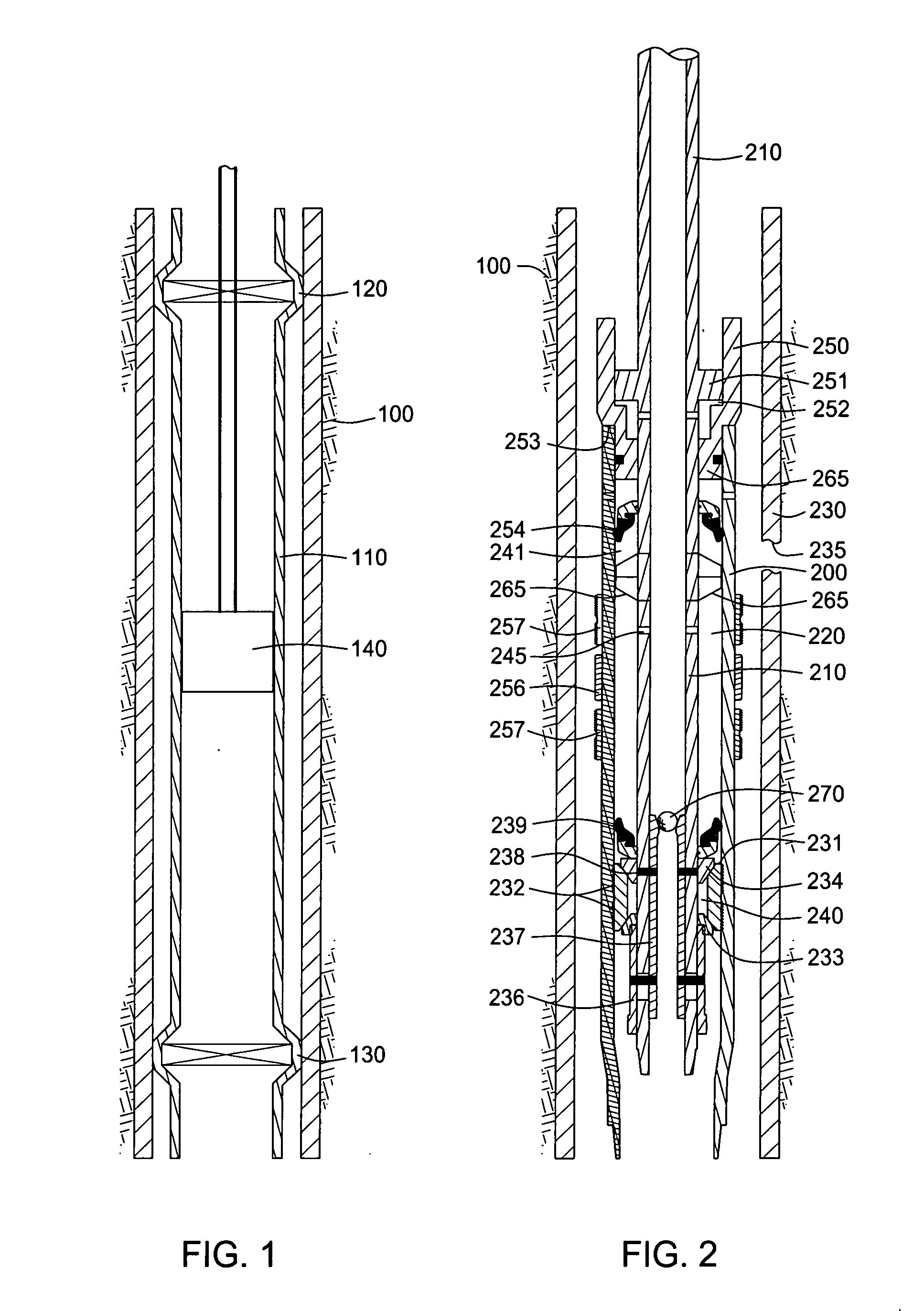
[0019]FIG. 1 illustrates a cross-sectional view of a wellbore 100 and a tubular 110 disposed therein. The tubular 110 can be casing or any other type of tubular used in downhole drilling operations, such as a liner or a patch. First and second fixed locations 120, 130 spaced apart along the length of the tubular 110 substantially prevent axial movement of the tubular 110 in the wellbore 100 such that the distance between the fixed locations 120, 130 cannot vary. The fixed locations 120, 130 can be achieved by any method or combination of methods known in the art, such as by using anchors or slips on an outside of the tubular 110 to engage a surrounding surface, by selectively expanding the tubular 110 at one or both of the fixed locations 120, 130 into frictional contact with the surrounding surface or by locating the bottom of the tubular 110 on a stop such as a plug, a packer or a bottom of the borehole (see, FIGS. 9-12). In the embodiment shown in FIG. 1, the fixed locations 120,...


PUM


Abstract

Methods and apparatus for expanding a tubular with the aid of a compressive force are disclosed. A tubular is run into a wellbore. While the tubular is in a compressive state, the tubular is expanded into its desired form. The expanded tubular can be used for multiple downhole functions such as completing multilateral junctions in a wellbore, patching apertures in a wellbore and lining a wellbore.

Description

BACKGROUND OF THE INVENTION [0001] 1. Field of the Invention [0002] Embodiments of the invention generally relate to expanding tubulars in a wellbore. More particularly, embodiments of the invention relate to the expansion of the tubulars enhanced by use of compressive forces applied to the tubulars. [0003] 2. Description of the Related Art [0004] Hydrocarbon and other wells are completed by forming a borehole in the earth and then lining the borehole with pipe or casing to form a wellbore. After a section of wellbore is formed by drilling, a section of casing is lowered into the wellbore and temporarily hung therein from the surface of the well. Using apparatus known in the art, the casing is cemented into the wellbore by circulating cement into the annular area defined between the outer wall of the casing and the borehole. The combination of cement and casing strengthens the wellbore and facilitates the isolation of certain areas of the formation behind the casing for the producti...

Claims


Application Information

Patent Timeline
Patent Type & Authority Applications(United States)
IPC IPC(8): E21B23/00
CPCE21B41/0042E21B43/105E21B43/103E21B43/10
Inventor RING, LEVMETCALFE, PAULHARRALL, SIMONHILLIS, DAVID
Owner WEATHERFORDLAMB
Why Eureka
Try Eureka