
Axial rotary eddy current brake with adjustable braking force

Inactive Publication Date: 2007-01-04
MAGNETAR TECH
View PDF58 Cites 49 Cited by
  • Summary
  • Abstract
  • Description
  • Claims
  • Application Information

AI Technical Summary

Benefits of technology

[0014] More particularly, the member may be comprised with concentric rings of different materials having different electrical conduction in order to alter the eddy current resistance and apparatus may

Problems solved by technology

This type of mechanism becomes complex, costly and is susceptible to failure.
Rotary eddy current brakes which utilize permanent magnets have in the past, been very power limited, and have been used mostly on exercise equipment or small machinery.
If a varying torque is required in response to a constant speed, varying the torque was not possible without utilizing an electric control apparatus to over ride the permanent magnets.
Conversely, if a constant torque is required in response to a varying speed, that function was also not possible without utilizing an electrical control apparatus to over ride the permanent magnets.

Method used


Image

  • Axial rotary eddy current brake with adjustable braking force
  • Axial rotary eddy current brake with adjustable braking force
  • Axial rotary eddy current brake with adjustable braking force

Examples


embodiment 156

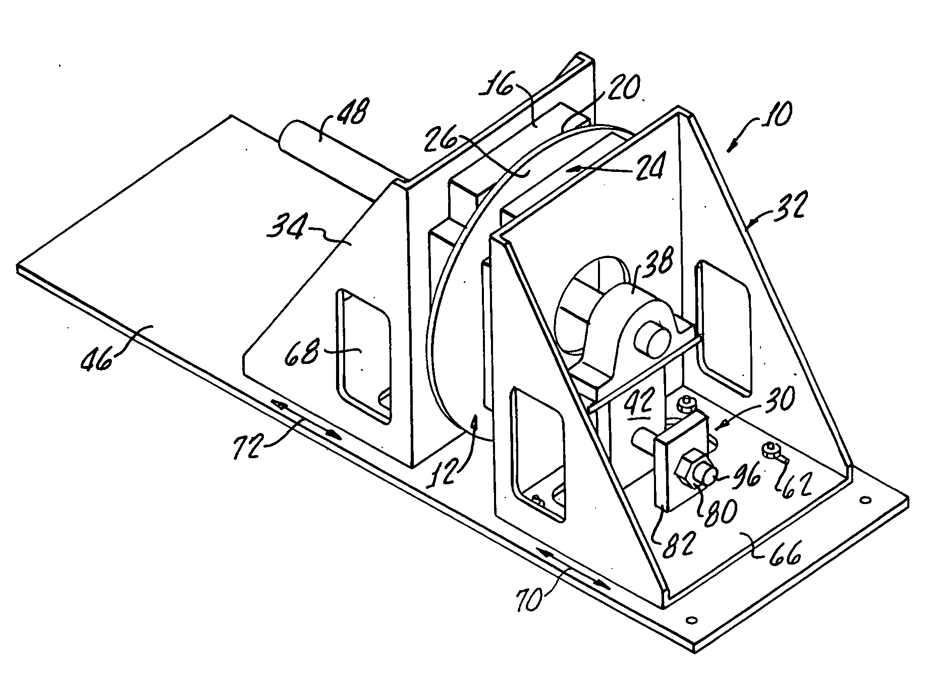
[0050] An alternative embodiment 156 is similar to the embodiment shown in FIGS. 9 and 9a with inner and outer rows 157, 158 radially adjustable by a screw mechanism 159, only one being shown for clarity, as indicated by an arrow A.

embodiment 160

[0051] With reference to FIGS. 11 and 11a there is shown an alternative embodiment 160. The magnet 162, 164, 166, 168 configuration in which the magnets 162, 164, 166, 168 are movable along the longitudinal axes 172, 174, 176, 178 as indicated by arrows 182, 184, 186, 188 which provides structure for varying the magnetic coupling between the magnets 162, 164, 166, 168 and a member 12 in order to vary eddy current resistance opposing rotation of the member 12. The magnets 162, 164, 166, 168 may be slidably mounted on the frame 32 in any conventional manner.

embodiment 192

[0052]FIG. 12 illustrates another embodiment 192 in accordance with the present invention utilizing multiple members 194, 196 mounted on a shaft 198 with the plurality of magnets 202, 204, 206, 208 of any of the hereinbefore described configurations and supported by a frame, not shown, similar to the frame of 32 hereinabove described.


PUM


Abstract

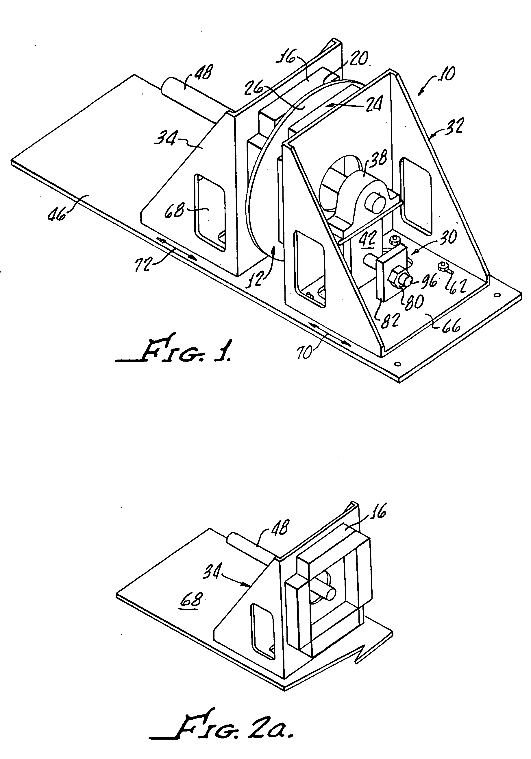
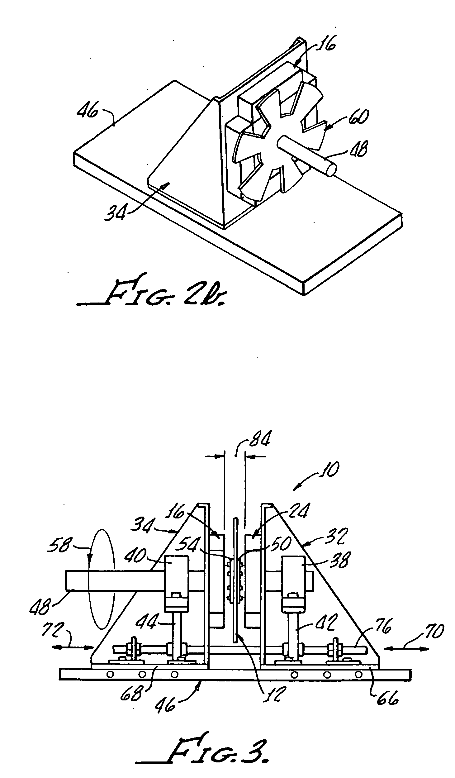
The present invention relates to an axial adjustable, rotary brake device using eddy current resistance, having an annular rotating conductive reaction member fastened on a central axle, having a frame, and fitted with permanent magnets disposed on either one side or both sides of said member, wherein the magnets produce a magnetic field between the magnet arrays, and through the member. Relative motion of the member and magnets produces eddy current resistance opposing the movement of the member. The magnets are mounted such that their respective positions relative to each other and thus to the intermediate conductive member can be changed by an adjusting Structure to increase or decrease the space between magnets and member, (air gap), distance from the rotational center or their relationship to each other. Various other configurations for changing the spatial relationship of magnets and members are presented which can be employed to produce many embodiments and variations of the present invention.

Description

[0001] The present application claims priority from U.S. Ser. No. 60 / 695,708 filed Jun. 30, 2005 which is to be incorporated herewith in its entirety by this specific reference thereto.[0002] This invention relates to industrial equipment such as drive systems, conveyors, lifting hoists, paper rollers, metal strip rolling mills, moving equipment, elevators, vehicles and the like and more particularly to an eddy current brake for providing a constant or variable torque for controlling the such equipment. [0003] Rotary eddy current brakes have been employed in many industrial applications, such as brakes, power transmission, or damping systems. The main advantage of such brakes, with respect to traditional mechanical friction brakes, retarding devices or tensioners, is represented by the absence of friction and the associated replacement or failure of brake components. [0004] Prior art rotary eddy current brakes are for the most part electromagnetic devices that generally have no resi...

Claims


Application Information

Patent Timeline
IPC IPC(8): B60L7/10
CPCH02K49/046
Inventor PRIBONIC, EDWARD M.THOMPSON, MARC T.
Owner MAGNETAR TECH
Learn More