Method and apparatus for use in camera and systems employing same

a technology of digital camera and camera body, applied in the field of digital imaging, can solve the problems of inability to accept the size or cost associated with putting stand-alone digital camera quality into pocket sized phones, conflicting needs,

Active Publication Date: 2007-01-04
INTELLECTUAL VENTURES II
View PDF70 Cites 335 Cited by
  • Summary
  • Abstract
  • Description
  • Claims
  • Application Information

AI Technical Summary

Benefits of technology

[0070] In one embodiment, providing relative movement includes moving the at least one portion of the first optics portion by an amount less than two times a width of one photo detector in the first array of photo detectors.
[0071] In another embodiment, providing relative movement includes moving the at least one portion of the first optics portion by an amount less than 1.5 times a width of one photo detector in the first array of photo detectors.
[0072] In another embodiment, providing relative movement includes moving the at least one portion of the first optics portion by an amount less than a width of one photo detector in the first array of photo detectors.
[0073] In some aspects, the movement may include movement in one or more of various

Problems solved by technology

These market needs can often be in conflict: higher performance often requires larger size, improved features can require higher cost as well as a larger size, and conversely, reduced cost and/or size can come at a penalty in performance and/or features.
As an example, consumers look for higher quality images from their cell phones, but are unwilling to accept the size or cost associated with putting stand-alone digital camera quality into their pocket sized phones.
A

Method used


Image

  • Method and apparatus for use in camera and systems employing same
  • Method and apparatus for use in camera and systems employing same
  • Method and apparatus for use in camera and systems employing same

Examples


Embodiment Construction

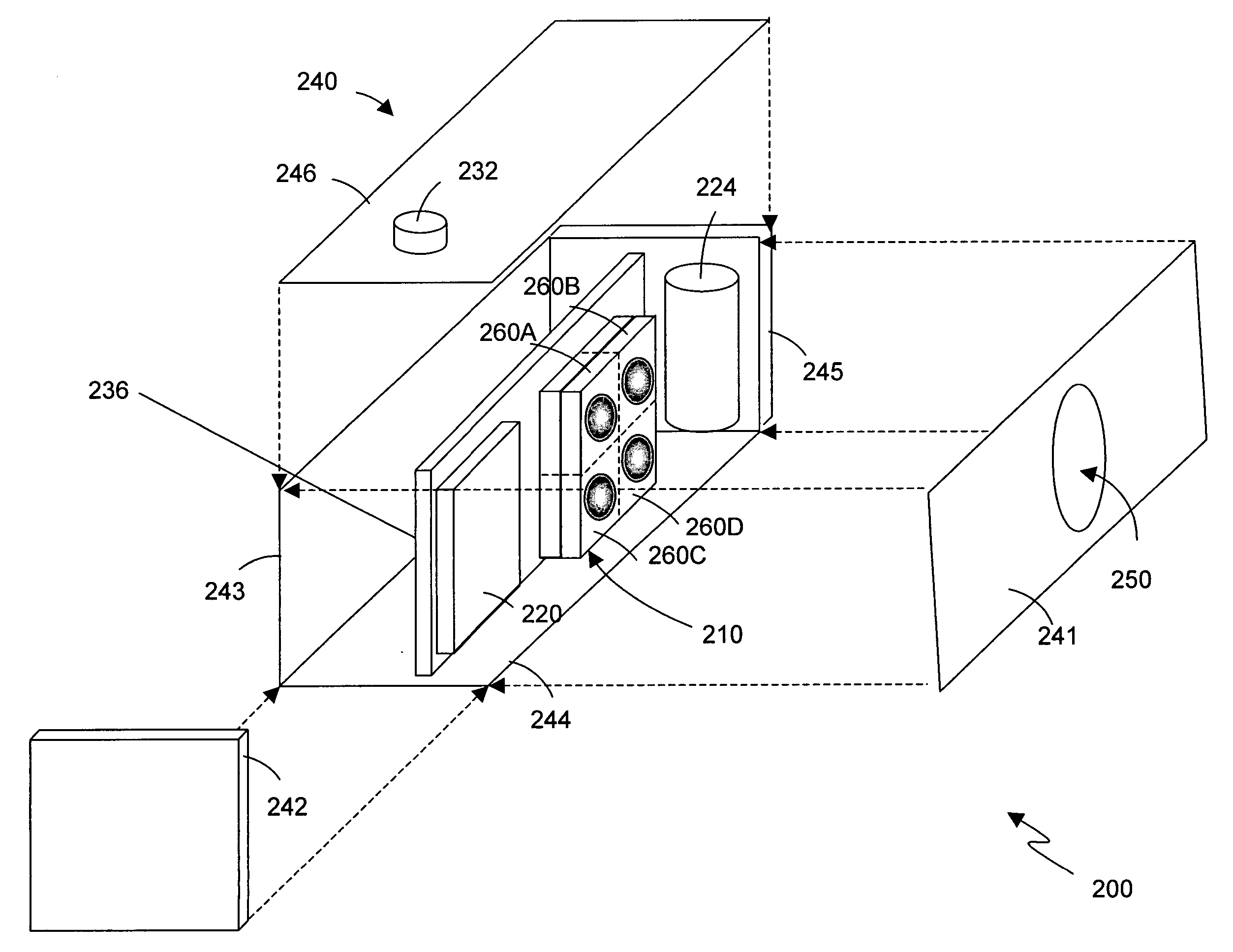
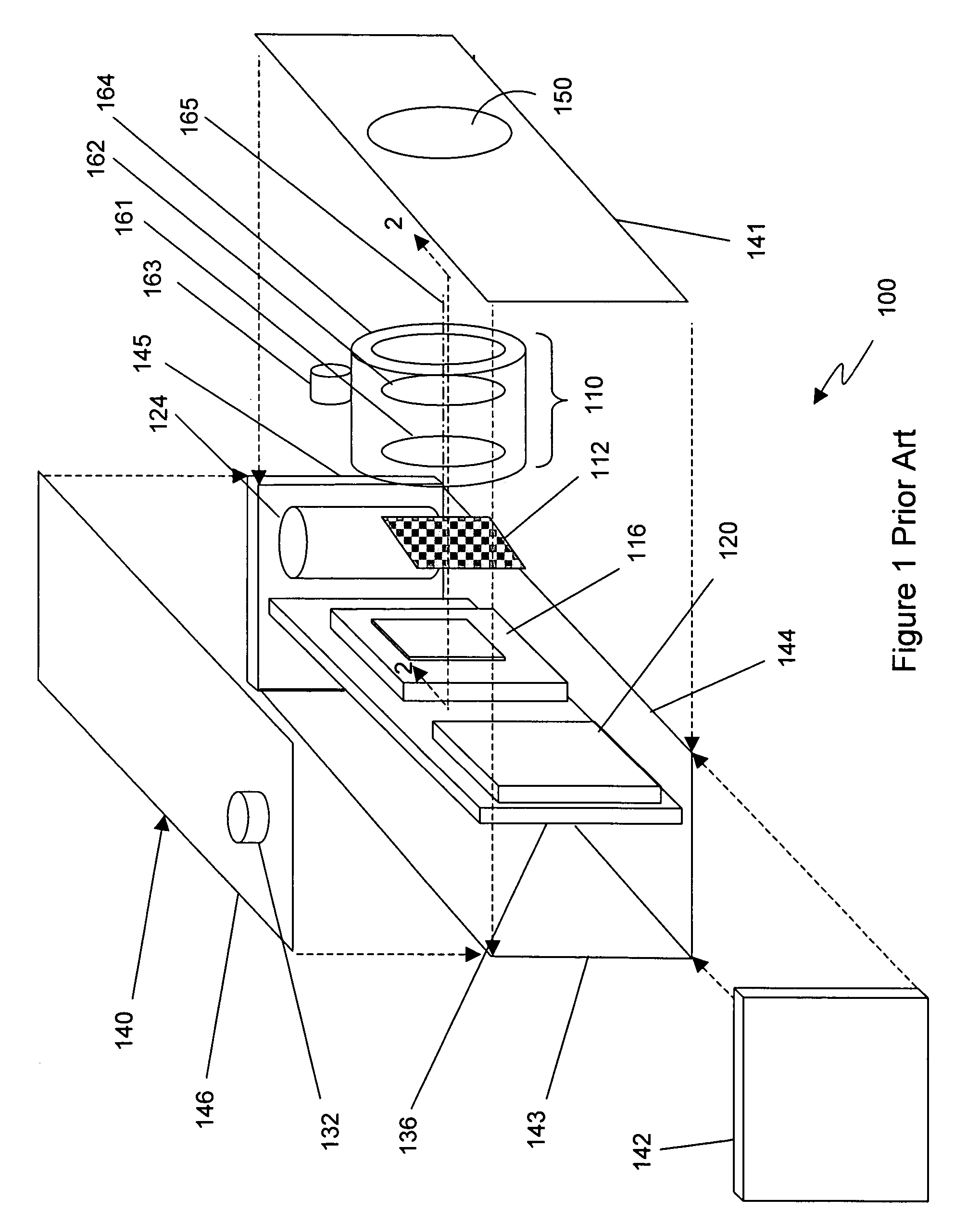
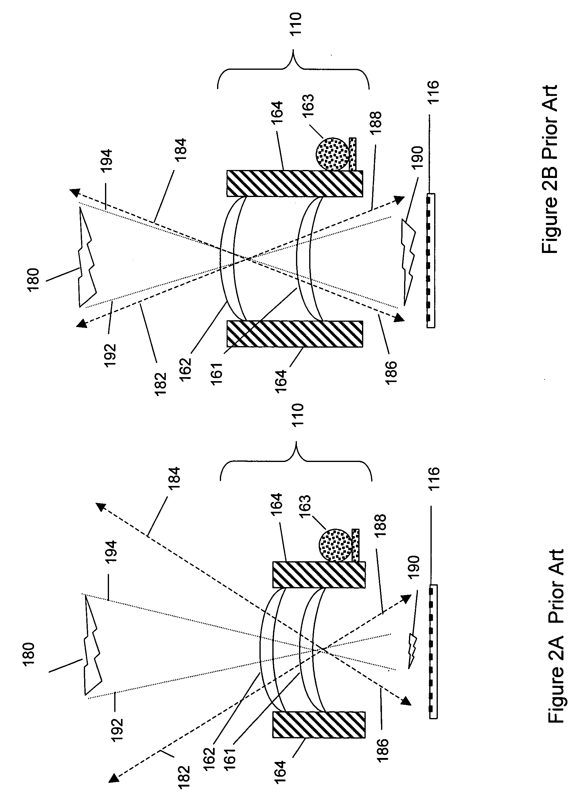
[0372]FIG. 1 shows a prior art digital camera 100 that includes a lens assembly 110, a color filter sheet 112, an image sensor 116, an electronic image storage media 120, a power supply 124, a peripheral user interface (represented as a shutter button) 132, a circuit board 136 (which supports and electrically interconnects the aforementioned components), a housing 140 (including housing portions 141, 142, 143, 144, 145 and 146) and a shutter assembly (not shown), which controls an aperture 150 and passage of light into the digital camera 100. A mechanical frame 164 is used to hold the various parts of the lens assembly 110 together. The lens assembly 110 includes lenses 161, 162 and one or more electromechanical devices 163 to move the lenses 161, 162 along a center axis 165. The lenses 161, 162 may be made up of multiple elements bonded together to form an integral optical component. Additional lenses may be employed if necessary. The electromechanical device 163 portion of the len...


PUM


Abstract

There are many inventions described herein. Some aspects are directed to methods and/or apparatus to provide relative movement between optics, or portion(s) thereof, and sensors, or portion(s) thereof, in a digital camera. The relative movement may be in any of various directions. In some aspects, relative movement between an optics portion, or portion(s) thereof, and a sensor portion, or portion(s) thereof, are used in providing any of various features and/or in the various applications disclosed herein, including, for example, but not limited to, increasing resolution, optical and electronic zoom, image stabilization, channel alignment, channel-channel alignment, image alignment, lens alignment, masking, image discrimination, range finding, 3D imaging, auto focus, mechanical shutter, mechanical iris, multi and hyperspectral imaging, and/or combinations thereof. In some aspects, movement is provided by actuators, for example, but not limited to MEMS actuators, and by applying appropriate control signal thereto.

Description

RELATED APPLICATIONS [0001] This application claims priority to U.S. Provisional Application Ser. No. 60 / 695,946, entitled “Method and Apparatus for use in Camera and Systems Employing Same”, filed Jul. 1, 2005 (hereinafter, the “Method and Apparatus for use in Camera and Systems Employing Same” provisional application), the entirety of which is expressly incorporated by reference herein.FIELD OF THE INVENTION [0002] The field of the invention is digital imaging. BACKGROUND OF THE INVENTION [0003] The recent technology transition from film to “electronic media” has spurred the rapid growth of the imaging industry with applications including still and video cameras, cell phones, other personal communications devices, surveillance equipment, automotive applications, computers, manufacturing and inspection devices, medical appliances, toys, plus a wide range of other and continuously expanding applications. The lower cost and size of digital cameras (whether as stand-alone products or ...

Claims


Application Information

Patent Timeline
IPC IPC(8): G02B13/16
CPCG02B7/04H04N19/00G02B13/0035G02B13/009G03B3/00G03B5/00G03B13/18G03B33/04G03B33/16G03B35/08G03B35/18G03B2205/0007G06T1/0007H01L27/14618H01L27/14621H01L27/14625H01L27/14627H01L27/14634H01L27/1469H01L31/0232H04N5/2253H04N5/2254H04N5/2257H04N5/232H04N5/23212H04N5/23248H04N5/23287H04N5/23296H04N5/332H04N9/097G02B7/102H01L2924/0002H01L31/02325H04N23/57H04N23/55H04N23/54H04N23/673H04N23/68H04N23/687H04N23/69H04N25/41H04N23/11H04N23/16H04N23/843H01L2924/00
Inventor OLSEN, RICHARD IANSATO, DARRYL L.MOLLER, BORDENVITOMIROV, OLIVERABRADY, JEFFREY A.GUNAWAN, FERRYOTEN, REMZISUN, FENG-QINGGATES, JAMES
Owner INTELLECTUAL VENTURES II
Why Eureka
Try Eureka