Laminar flow gas curtains for lithographic applications

a gas curtain and laminar flow technology, applied in the field of lithography, can solve the problems of inefficiency of available gas curtain systems, inefficient use, and add to the overall cost of lithographic throughpu

Active Publication Date: 2007-01-04
ASML HLDG NV
View PDF4 Cites 9 Cited by
  • Summary
  • Abstract
  • Description
  • Claims
  • Application Information

AI Technical Summary

Benefits of technology

[0006] According to the present invention, the nozzle limits gaseous mixing that occurs during purging of a gaseous volume. This is achieved, in part, by forcing the purge gas through the plurality of flow conditioning channels so that the purge gas is made to flow laminarly through the flow conditioning channels. The gaseous flow-field exiting the flow conditioning channels is axially directional and maintains its stream-tube direction after it exits the conditioning channels with little to no mixing occurring between tubular streamlines throughout a prescribed effective throw distance. Forcing the gas through the flow conditioning channels increases the pressure drop, which is used to achieve a laminar flow with a clean parabolic velocity profile.

Problems solved by technology

Available gas curtain systems, however, are inefficient because of the ease with which the purging gas mixes with environmental gases during the purge process.
The gas used to form a gas curtain is a consumable, and the inefficient use of gas by available gas curtain systems adds to the overall cost of lithographic throughput.

Method used


Image

  • Laminar flow gas curtains for lithographic applications
  • Laminar flow gas curtains for lithographic applications
  • Laminar flow gas curtains for lithographic applications

Examples


Embodiment Construction

[0019] The present invention provides laminar flow gas curtains for use in lithographic applications. In the detailed description of the invention that follows, references to “one embodiment”, “an embodiment”, “an example embodiment”, etc., indicate that the embodiment described may include a particular feature, structure, or characteristic, but every embodiment may not necessarily include the particular feature, structure, or characteristic. Moreover, such phrases are not necessarily referring to the same embodiment. Further, when a particular feature, structure, or characteristic is described in connection with an embodiment, it is submitted that it is within the knowledge of one skilled in the art to effect such feature, structure, or characteristic in connection with other embodiments whether or not explicitly described.

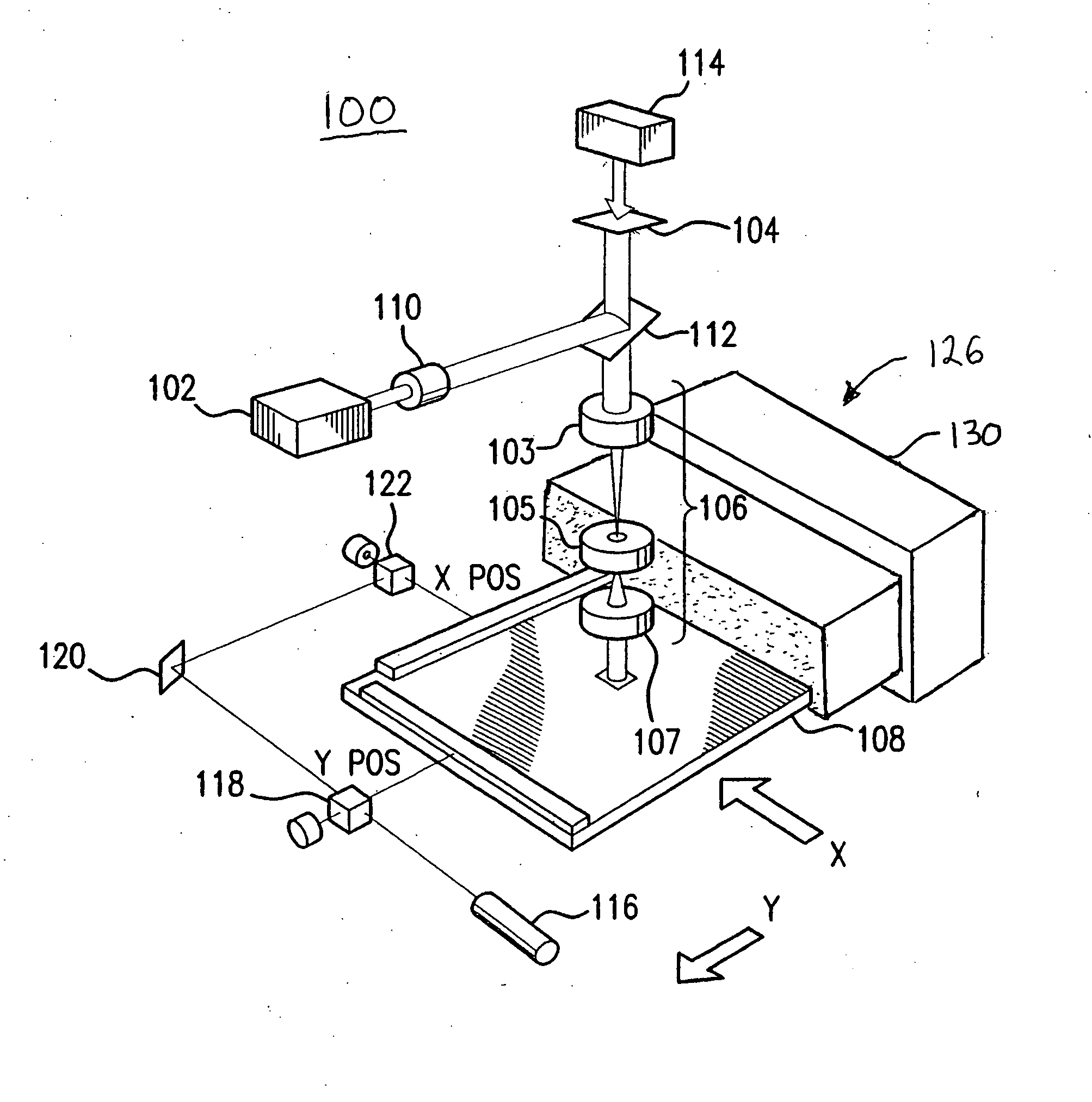
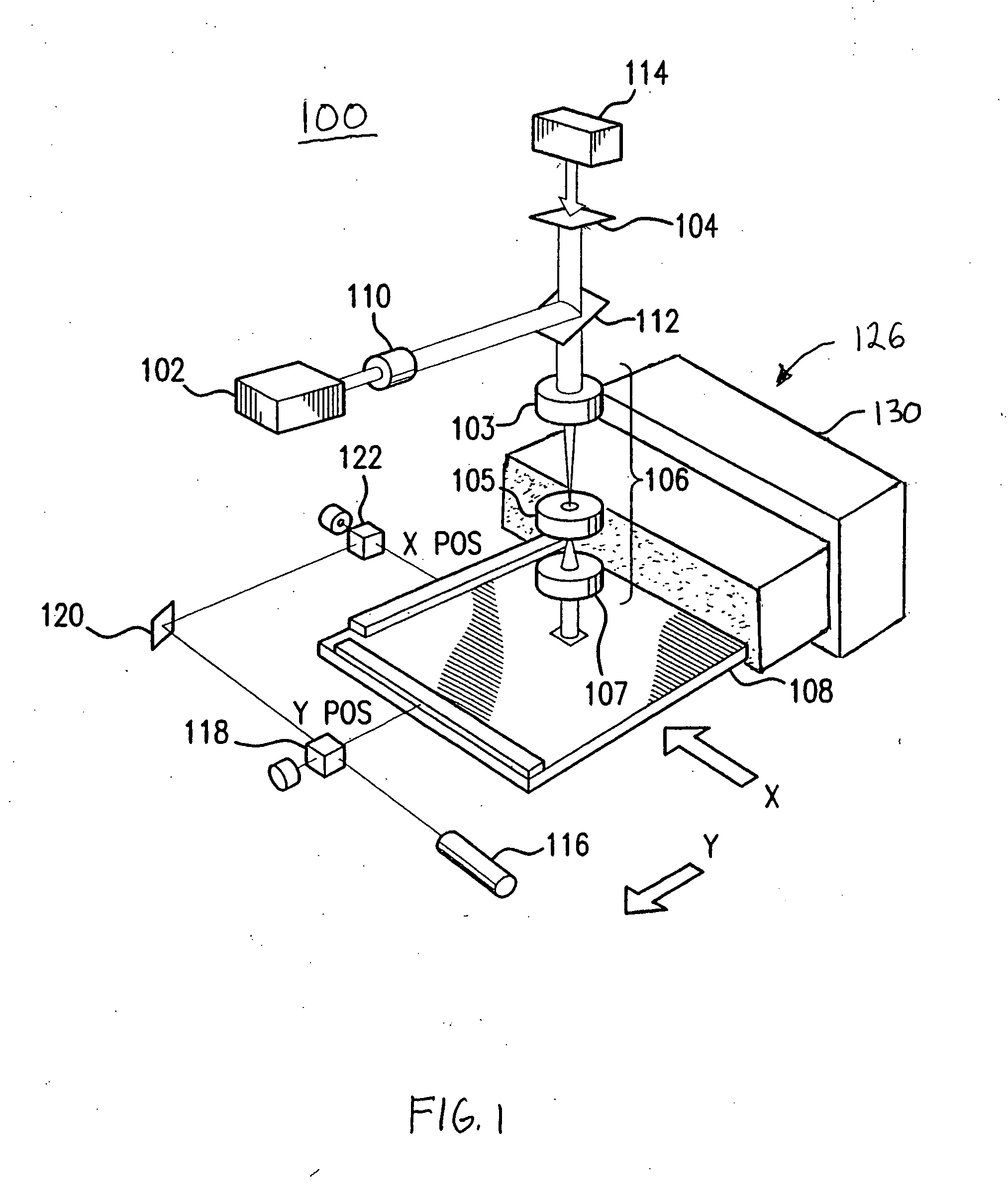
[0020]FIG. 1 is a schematic diagram of a lithography tool 100 according to an embodiment of the present invention. Tool 100 includes an illumination source 102,...


PUM


Abstract

Laminar flow gas curtains for use in lithographic applications. In an embodiment, a gas curtain system includes a nozzle that enhances the fluidic purge process. The nozzle includes a first housing, a second housing, a flow distribution plate, and a plurality of flow conditioning channels. The first housing has an inlet for receiving a gas and encloses a first volume. The second housing encloses a second volume and is fluidly coupled to the first housing. The flow distribution plate controls the flow of gas from the first volume to the second volume. The plurality of flow conditioning channels are disposed within a portion of the second volume and are used to discharge the gas that forms the gas curtain. The length of the flow conditioning channels is selected to attenuate non-axial, gas velocity flow-vectors. The nozzle limits the gaseous mixing that occurs after the purge gas exits the nozzle channels and starts to purge a gaseous volume.

Description

FIELD OF THE INVENTION [0001] The present invention relates generally to lithography. More particularly, it relates to laminar flow gas curtains for lithography applications. BACKGROUND OF THE INVENTION [0002] Gas curtains are used in a variety of applications. In lithographic applications, they are used to maintain required gaseous purity levels within selected components such as the wafer stage and the wafer handling systems. Another example of gas curtain use is to provide thermally stable environments to facilitate interferometry measurements. [0003] Available gas curtain systems, however, are inefficient because of the ease with which the purging gas mixes with environmental gases during the purge process. The gas used to form a gas curtain is a consumable, and the inefficient use of gas by available gas curtain systems adds to the overall cost of lithographic throughput. [0004] What is needed for lithographic applications are new gas curtain systems that overcome the limitatio...

Claims


Application Information

Patent Timeline
Patent Type & Authority Applications(United States)
IPC IPC(8): G03B27/52
CPCG03F7/70908G03F7/70716
Inventor VOGEL, HERMANPARISI, MICHAEL J.
Owner ASML HLDG NV
Why Eureka
Try Eureka