Optical scanner and image-forming device
a technology of optical scanner and image, which is applied in the direction of printing, inking apparatus, instruments, etc., can solve the problems of increasing the rotational speed of the polygon mirror, generating greater vibration in the polygon mirror unit, reducing the quality of the electrostatic latent image formed thereon, etc., to achieve the effect of reducing vibration, increasing the rotational speed of the deflecting unit, and not increasing the structural complexity of the support fram
- Summary
- Abstract
- Description
- Claims
- Application Information
AI Technical Summary
Benefits of technology
Problems solved by technology
Method used
Image
Examples
first embodiment
[0027] First, a laser printer 1 according to the present invention will be described.
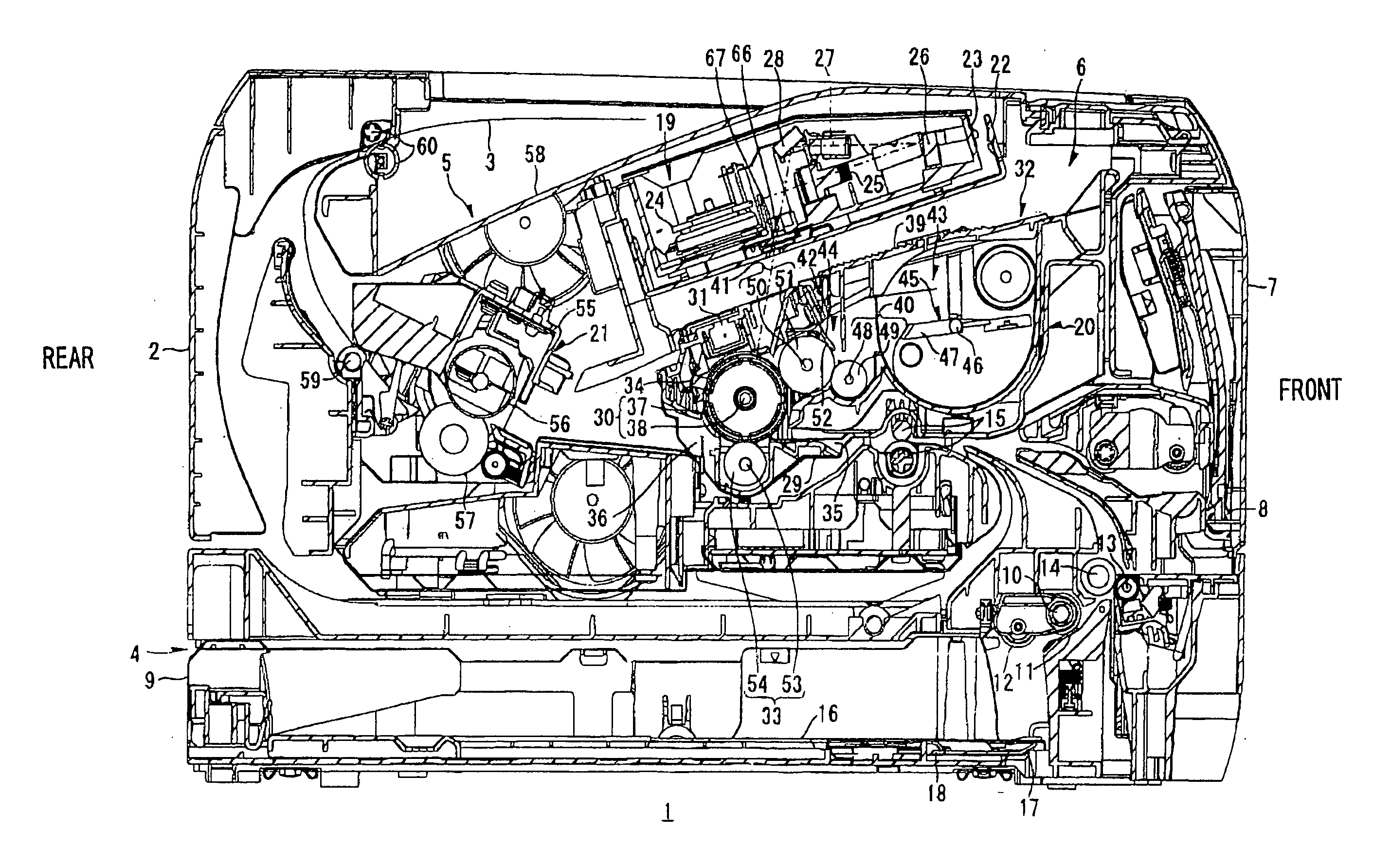
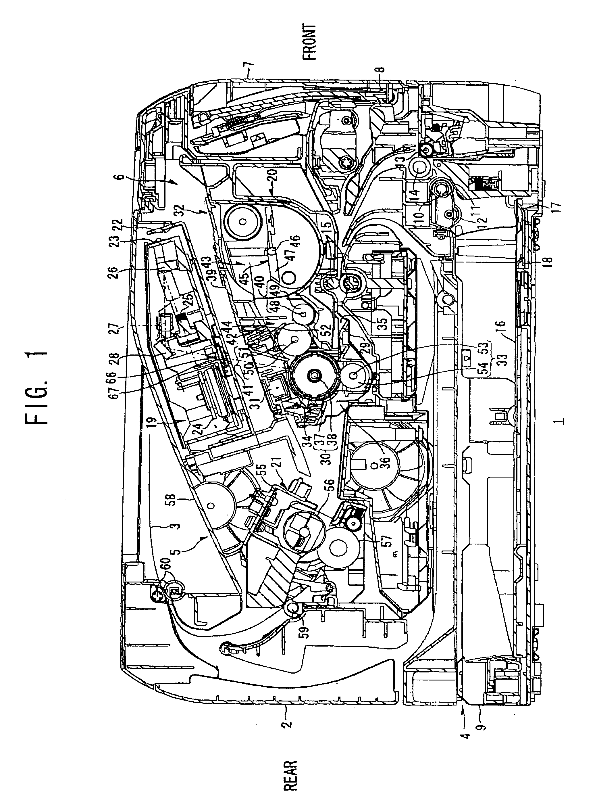
[0028] As shown in FIG. 1, the laser printer 1 includes a feeding unit 4 for supplying sheets of paper 3, an image-forming unit 5 for forming images on the paper 3 supplied by the feeding unit 4, and a main casing 2 housing the feeding unit 4 and the image-forming unit 5.
[0029] The laser printer 1 also includes an access opening 6 formed in one side wall of the main casing 2 for inserting and removing a process cartridge 20 described later, and a front cover 7 capable of opening and closing over the access opening 6. The front cover 7 is rotatably supported by a cover shaft 8 inserted through a bottom edge of the front cover 7. Accordingly, when the front cover 7 is rotated closed about the cover shaft 8, the front cover 7 covers the access opening 6 as shown in FIG. 1. When the front cover 7 is rotated open about the cover shaft 8, the access opening 6 is exposed, enabling the process cartridge 20...
second embodiment
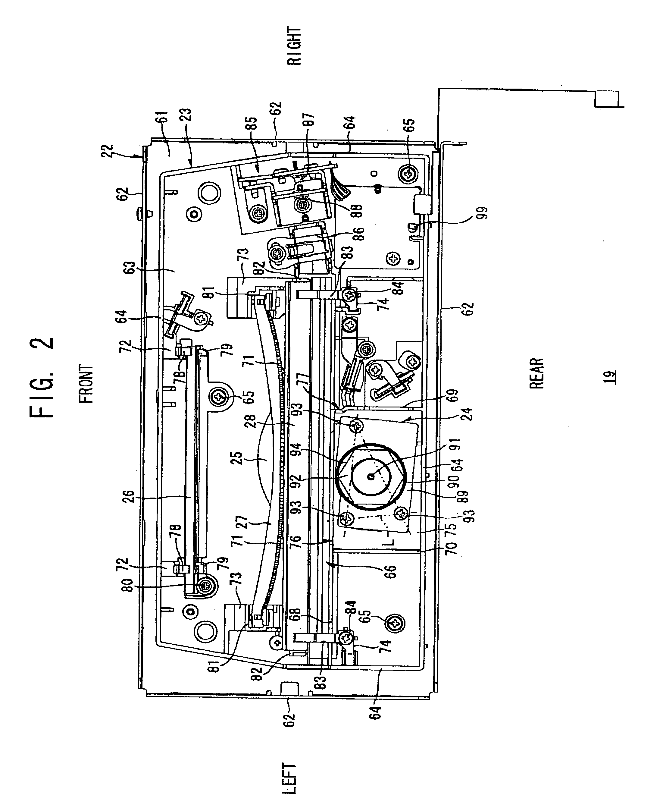
[0127] Next, a scanning unit 119 according to the present invention will be described FIG. 7 is a perspective view schematically illustrating the scanning unit 119, wherein like parts and components are designated with the same reference numerals to avoid duplicating description.
[0128] In the structure shown in FIG. 7, an aperture plate 96 is disposed between the light source 85 and the cylindrical lens 86. The aperture plate 96 is formed with a rectangular aperture 95 that is wider than the input side opening 77 in the main scanning direction. A laser beam emitted from the light source 85 first passes through the aperture 95 of the aperture plate 96 and subsequently passes through the cylindrical lens 86 and the input side opening 77 before striking the polygon mirror 92.
[0129] By directing the laser beam through the aperture 95 of the aperture plate 96, this construction can restrict the width of the laser beam in both the main scanning direction and the subscanning direction. In...
third embodiment
[0131] Next, a scanning unit 219 according to the present invention will be described. FIG. 8 is a perspective view schematically illustrating the scanning unit 219, wherein like parts and components are designated with the same reference numerals to avoid duplicating description.
[0132] In the structure shown in FIG. 8, an aperture plate 98 is disposed between the polygon mirror 92 and the fθ lens 25 The aperture plate 98 is formed with a rectangular aperture 97 elongated in the main scanning direction. With this construction, the laser beam deflected and scanned by the polygon mirror 92 passes through the aperture 97 of the aperture plate 98 prior to being incident on the fθ lens 25. Therefore, the aperture 97 of the aperture plate 98 restricts the width of the laser beam in the subscanning direction before the laser beam reaches the fθ lens 25.
[0133] With this construction, the input side opening 77 of the front-to-rear rib 69 restricts the width of the laser beam in the main sca...
PUM
 Abstract
Description
Claims
Application Information
 - R&D
- Intellectual Property
- Life Sciences
- Materials
- Tech Scout
- Unparalleled Data Quality
- Higher Quality Content
- 60% Fewer Hallucinations
Browse by: Latest US Patents, China's latest patents, Technical Efficacy Thesaurus, Application Domain, Technology Topic, Popular Technical Reports.
© 2025 PatSnap. All rights reserved.Legal|Privacy policy|Modern Slavery Act Transparency Statement|Sitemap|About US| Contact US: help@patsnap.com


