
Motion estimation circuit and operating method thereof

a motion estimation and circuit technology, applied in the field of motion estimation, can solve the problems of reducing unable to compute the sads simultaneously for image blocks with different sizes, and a large amount of digital video data, so as to reduce the number of selection circuits

Inactive Publication Date: 2007-01-04
NOVATEK MICROELECTRONICS CORP
View PDF42 Cites 13 Cited by
  • Summary
  • Abstract
  • Description
  • Claims
  • Application Information

AI Technical Summary

Benefits of technology

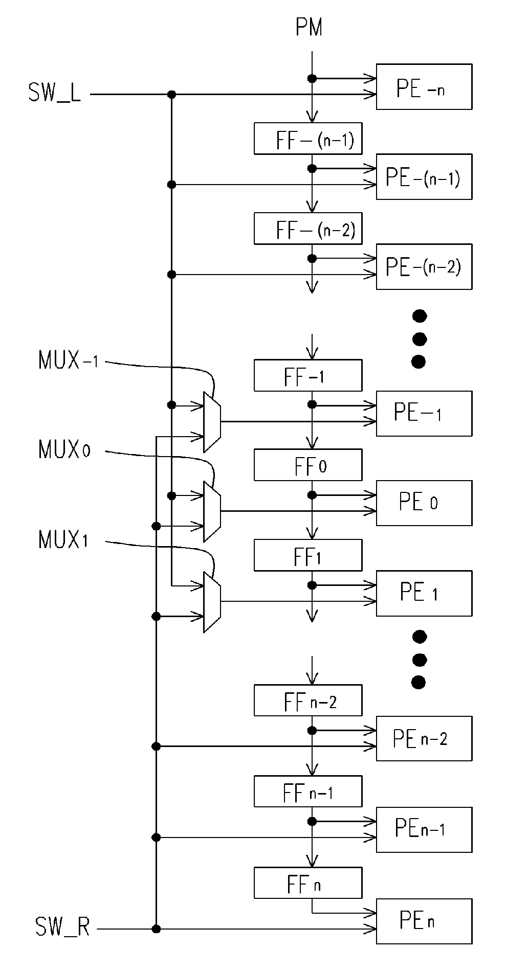
[0010] An object of the present invention is to provide a motion estimation circuit based on the systolic array architecture to enhance algorithm efficiency; wherein, a 4×4 pixel image block is taken as the basic unit for motion estimation. In this way, the motion estimation circuit of the present invention is able to support the standard H.264 and the motion estimation with tree structure and significantly reduces the number of selection circuits in a systolic array. Instead, only three selection circuits are needed for switching the data in left / right sector of the sub search windows.
[0011] Another object of the present invention is to provide an operating method of the motion estimation circuit so that the present invention can be exercised to a maximum degree.
[0016] Since the present invention uses systolic array architecture to perform computations of the motion estimation and uses a 4×4-pixel block as the basic unit for the motion estimation, the present invention is able to support the standard H.264 and the tree structured motion estimation. In addition, the present invention significantly reduces the number of selection circuits in a systolic array, which only three selection circuits are needed for switching the data in the left / right sector of the sub search windows. Each processing element in the motion estimation circuit of the present invention is used for computing, registering and accumulating the sum of absolute difference (SAD) for each 4×4-pixel sub block in the current block and the corresponded 4×4-pixel block in the search window, respectively. The SAD result for the current block and the corresponded block in the search window is also output by each processing element, respectively. Wherein, the current block can be image blocks with sizes of 1 6×16 pixels, 8×16 pixels, 16×8 pixels, 8×8 pixels, 8×4 pixels, 4×8 pixels and 4×4 pixels.

Problems solved by technology

In general, the data amount of digital video is tremendously huge.
On the other hand, a motion estimation circuit to efficiently meet such large computation is considerably complicated.
In particular, the newly revised standard H.264 has added image blocks with sizes of 8×16 pixels, 16×8 pixels, 8×4 pixels, 4×8 pixels and 4×4 pixels; the conventional technique fails to simultaneously compute SADs for image blocks with different sizes.
Furthermore, the conventional technique is only capable computing individually image blocks with 16×16 pixels or 8×8 pixels and fails to support motion estimation in the form of a tree structure.

Method used


Image

  • Motion estimation circuit and operating method thereof
  • Motion estimation circuit and operating method thereof
  • Motion estimation circuit and operating method thereof

Examples


Embodiment Construction

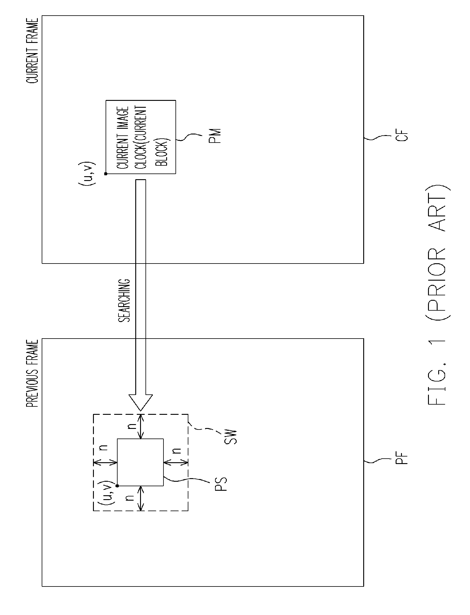
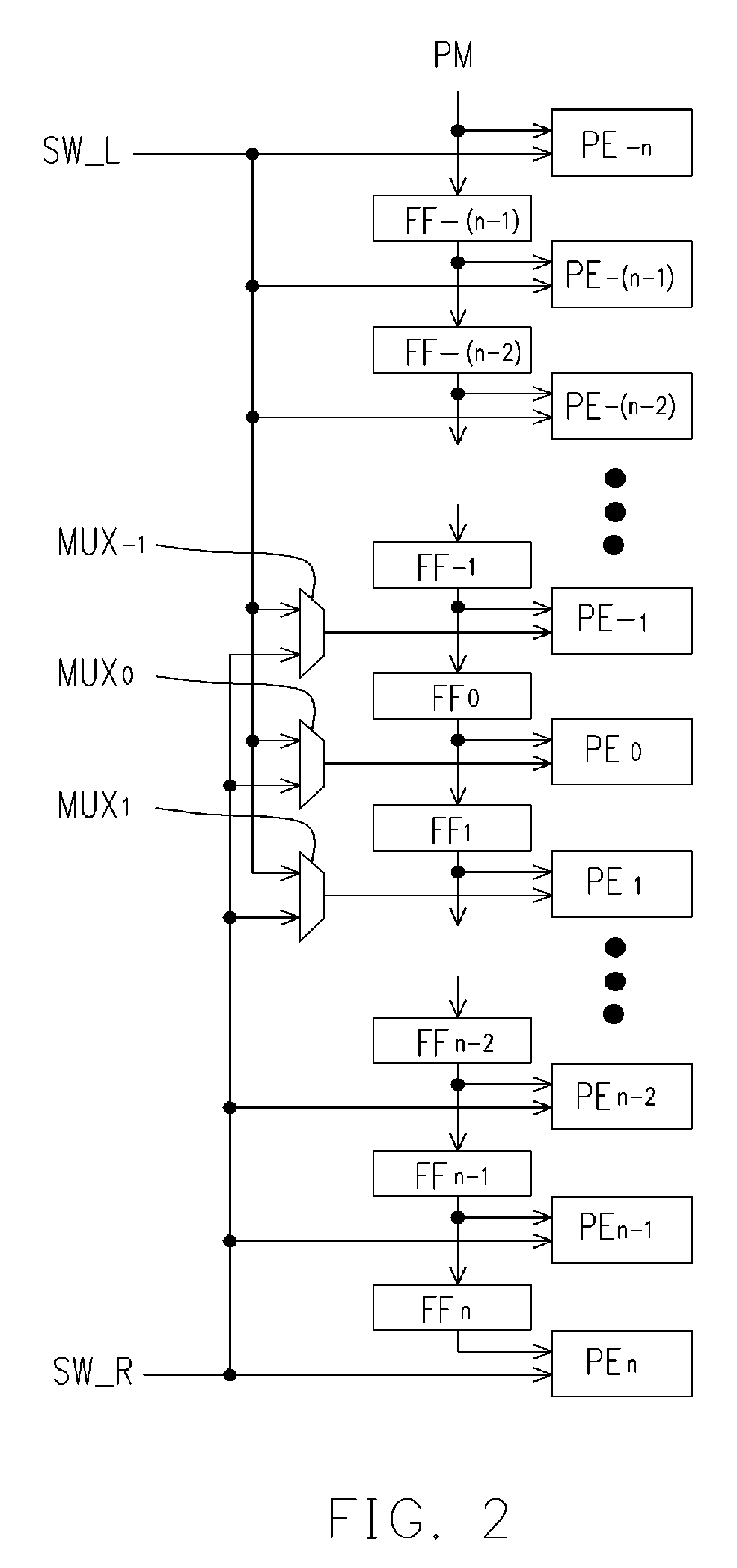
[0028]FIG. 2 is a schematic drawing of a motion estimation circuit having systolic array architecture according to an embodiment of the present invention. Referring to FIGS. 1 and 2, the motion estimation circuit includes processing elements PE−n˜PEn, data latches (for example, D-type flip-flops) FF−(n−1)˜FFn and selection circuits (for example, multiplexers) MUX−1˜MUX1. Wherein, n denotes a search range value corresponding to the current block in the search window and is an integer larger than 0.

[0029] Each processing element PE−n˜PEn receives the pixel element data in the current block (hereinafter “PM”) and the pixel element data of the corresponded block in the search window SW, performs a sum of absolute difference (SAD) computation on the pixel element data in the both blocks and outputs the result of the computation.

[0030] For convenience, it is assumed the current image block PM in FIG. 1 of the embodiment is a 16×16-pixel block. The 16×16-pixel block PM in FIG. 1 is virtu...


PUM


Abstract

The present invention provides a motion estimation circuit and an operating method thereof. The motion estimation circuit includes processing elements PEm (−n≦m≦n, n represents a search range), data latches FFk (−n<k≦n) and selection circuits MUXh (−1≦h≦1). The processing element receives a current block data and the corresponded block data in a search window and performs a comparison operation on the two block data. The output-end of FFk is coupled to an input-end of FFk+1 and a first input-end of PEk. The output-end of MUXh is coupled to a second input-end of PEh. Wherein, each 4×4-pixel sub block of the current block is input into PE−n and FF−(n−1), the left sector of the sub-search-window SW′ is input into the second input-ends of PE−n˜PE−2 and the first input-end of MUXh, and the right sector of the sub-search-window SW′ is input into the second input-ends of PE2˜PEn and MUXh.

Description

CROSS-REFERENCE TO RELATED APPLICATION [0001] This application claims the priority benefit of Taiwan application serial no. 94119772, filed on Jun. 15, 2005. All disclosure of the Taiwan application is incorporated herein by reference. BACKGROUND OF THE INVENTION [0002] 1. Field of Invention [0003] The present invention relates to motion estimation, and particularly to a motion estimation circuit having a systolic array architecture and the operating method thereof. [0004] 2. Description of the Related Art [0005] In general, the data amount of digital video is tremendously huge. To save the space for storing video data and the transmission bandwidth during transmitting video data, a video data compression must be implemented. To achieve the goal of reducing data, redundant information in a video data needs to be removed. For example, if a previous picture (or a “frame”) is similar with the next frame, the previous frame can be kept and the same contents in the next frame are removed...

Claims


Application Information

Patent Timeline
IPC IPC(8): H04N11/02H04N19/50H04N19/136H04N19/137H04N19/196H04N19/423H04N19/436H04N19/51
CPCH04N19/119H04N19/43H04N19/61H04N19/51
Inventor YANG, HSING-CHIEN
Owner NOVATEK MICROELECTRONICS CORP
Learn More