Ribbon hub and spool assembly

a technology of hub and spool, which is applied in the direction of printing and inking apparatus, etc., can solve the problems of awkward and difficult procedures, and the alignment can be very difficul

Inactive Publication Date: 2007-01-04
PRINTRONIX INCORPORATED
View PDF4 Cites 0 Cited by
  • Summary
  • Abstract
  • Description
  • Claims
  • Application Information

AI Technical Summary

Benefits of technology

[0011] According to one aspect of the present invention, a hub and spool assembly includes a hub having two or more tapered cantilever beam snaps, a tapered top portion, and rounded splines along the circumference of the hub, and a spool having a plurality of rounded and tapered splines along a tapered interior of the spool. Such a hub and spool assembly provides numerous advantages over conventional assemblies.
[0012] The plurality of cantilever beam snaps enables opposing forces to balance the loads when the beams are deflected during spool or cassette installation. A tapered, rounded, or smoothly blended crown or ridge on the top of the cantilever beam snaps lets the user more easily begin insertion of the hub into the hole of the spool. This also, in conjunction with the rounded splines of the hub and the rounded, tapered splines of the spool allows for self-alignment, resulting in an easier alignment of spool and hub. The tapered edge along the opening of the spool enables easy insertion of the hub. In addition, once “locked”, the geometry of the beam snaps and tapered edge allows the hub to be removed by simply pushing out the hub, thereby eliminating the need to directly depress the beam snaps.
[0013] In another embodiment, the crown of the beam snaps have a tapered lower portion so that the spool does not need to have a tapered edge along the opening. The tapered lower portion would rest against the spool when the hub and spool are “locked”. The tapered lower portion would then similarly allow the user to remove the hub by simply pushing out the hub, since the physical action of pushing out the hub causes the cantilever to depress for easy removal.

Problems solved by technology

Because it is a single beam, the force required to deflect the beam is not counter-balanced with an opposing force, making the procedure awkward and difficult. FIG. 5 shows spool 12 and hub 14 assembled and locked.
In a cartridge application, because the internal splines within the cartridge cannot be accessed or seen, this alignment can be very difficult if the deflection of a cantilever snap feature is involved.

Method used


Image

  • Ribbon hub and spool assembly
  • Ribbon hub and spool assembly
  • Ribbon hub and spool assembly

Examples


Embodiment Construction

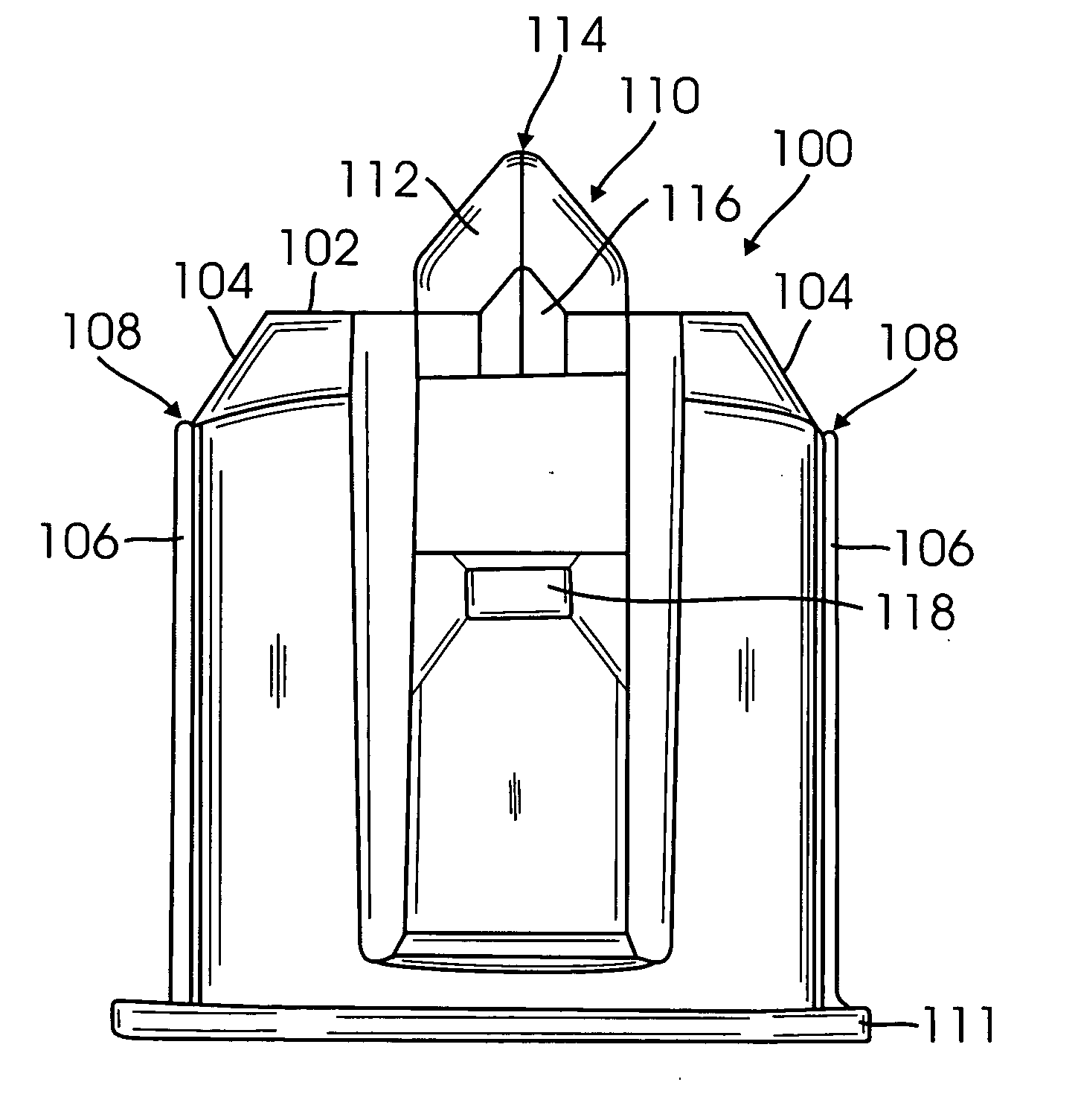
[0026] According to one embodiment of the present invention, a hub and spool assembly for a printer system includes a hub with at least two tapered cantilever beams, rounded splines, and a tapered top, and a spool having rounded and tapered splines and a tapered opening.

[0027]FIG. 6 is a side view of a hub 100 according to one embodiment of the invention. FIG. 7 is a perspective view of hub 100, and FIG. 8 is a top view of hub 100. Hub 100 can be a motor-driven hub for use in an impact printer system. In this embodiment, hub 100 has a top flat surface 102 with an angled or tapered portion 104 extending to the outer circumference of the hub. A plurality of splines 106 is located along the outer circumference of the hub, where splines 106 extend parallel to the axis of rotation. Each spline 106 has a rounded or curved top portion 108 at or near angled portion 104.

[0028] Hub 100 also has two opposing cantilever beams 110. Other embodiments can have more than two such beams. Beams 110...


PUM


Abstract

A ribbon hub and spool assembly includes a hub having at least two cantilever beams having a smooth, tapered, and curved crown, and a spool having curved and tapered splines. The cantilever beams balance the forces when inserting the hub into the spool, and the shape of the crowns of the hub and splines of the spool enable easy insertion and alignment of the hub and spool assembly.

Description

CROSS REFERENCE TO RELATED APPLICATIONS [0001] The present invention claims priority to U.S. Provisional Application Ser. No. 60 / 692,197, filed Jun. 17, 2005, and which is incorporated by reference in its entirety.BACKGROUND [0002] 1. Field of Invention [0003] The present invention relates to a printer ink ribbon spool and hub assembly. [0004] 2. Related Art [0005] Impact printers incorporate inked ribbon to supply ink for the printing process. Typically this inked ribbon is provided as a long length of fabric wound-up onto a supply spool, or it is stored inside a cartridge in one long continuous loop. During the printing process, the inked ribbon, whether on spools or in a cartridge, is pulled through the printing station by means of one or more motor-driven hubs that engage splines in the spools or cartridge. [0006] The ribbon system, including the inked fabric and its associated cartridge or set of spools, is a consumable product that must be periodically replaced. Replacement of...

Claims


Application Information

Patent Timeline
IPC IPC(8): B65H75/00
CPCB41J35/28B41J33/00
Inventor WHITE, DENNIS R.
Owner PRINTRONIX INCORPORATED
Why Eureka
Try Eureka