Remote control sweeper

a sweeper and remote control technology, applied in the field of sweepers, can solve the problems of inability to take care of the hard-to-reach areas of brooms and electric sweepers, inefficient cleaning of a large area of floors, and easy back pain,

Inactive Publication Date: 2007-01-11
GUTEN ELECTRONICS IND
View PDF10 Cites 150 Cited by
  • Summary
  • Abstract
  • Description
  • Claims
  • Application Information

AI Technical Summary

Benefits of technology

[0006] To overcome the inconvenience and shortcomings of the prior art, the present invention provides a lightweight and convenient remote control sweeper.
[0007] Therefore, it is a primary objective of the invention to provide a sweeper whose moving direction can be controlled to clean up dirt and collect dust. The present invention is an effort-saving, convenient, easy-to-operate sweeper, particularly suitable for people who have a walking problem.
[0008] A secondary objective of the present invention is to provide a sweeper with a small size and a flat shape that can freely sweep and pass through a small, short and hard-to-reach area.
[0010] A further objective of the present invention is to provide a sweeper whose brush can be replaced by users. Users can change the brush to an appropriate one according to actual needs.

Problems solved by technology

The common tool used for sweeping floor is a broom, which can be used to clean up a small area of floor, but using a broom to clean up a large area of floor is very inefficient.
Even for general users, operating or pushing the machine will cause backaches easily.
Furthermore, the broom and electric sweepers cannot take care of the hard-to-reach areas such as a place with many obstacles or an area with a short height (under a seat, table or furniture, etc), since the structure and the volume of the broom or sweeper are restricted and thus cannot clean up the hard-to-reach areas.

Method used


Image

  • Remote control sweeper
  • Remote control sweeper
  • Remote control sweeper

Examples


Embodiment Construction

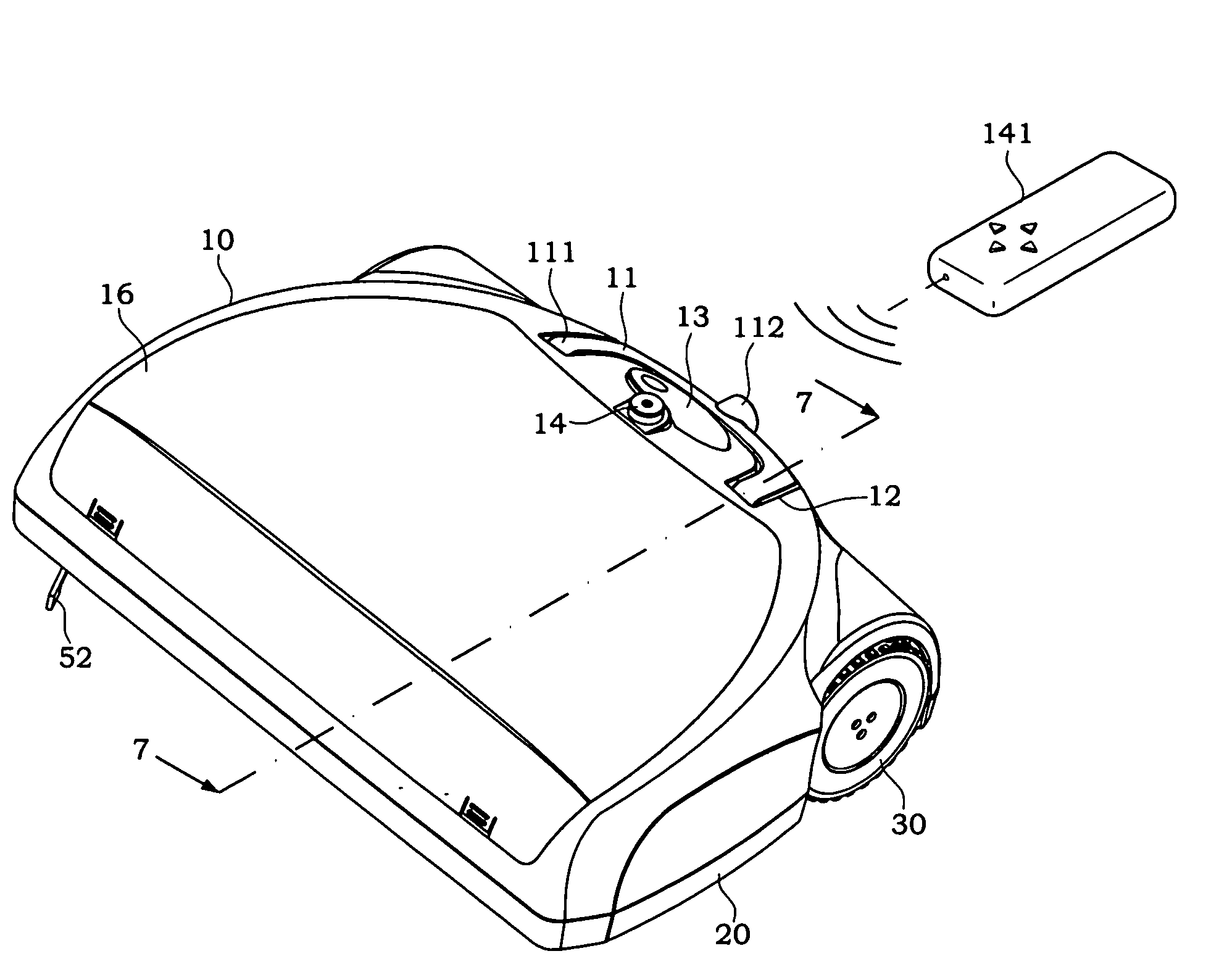
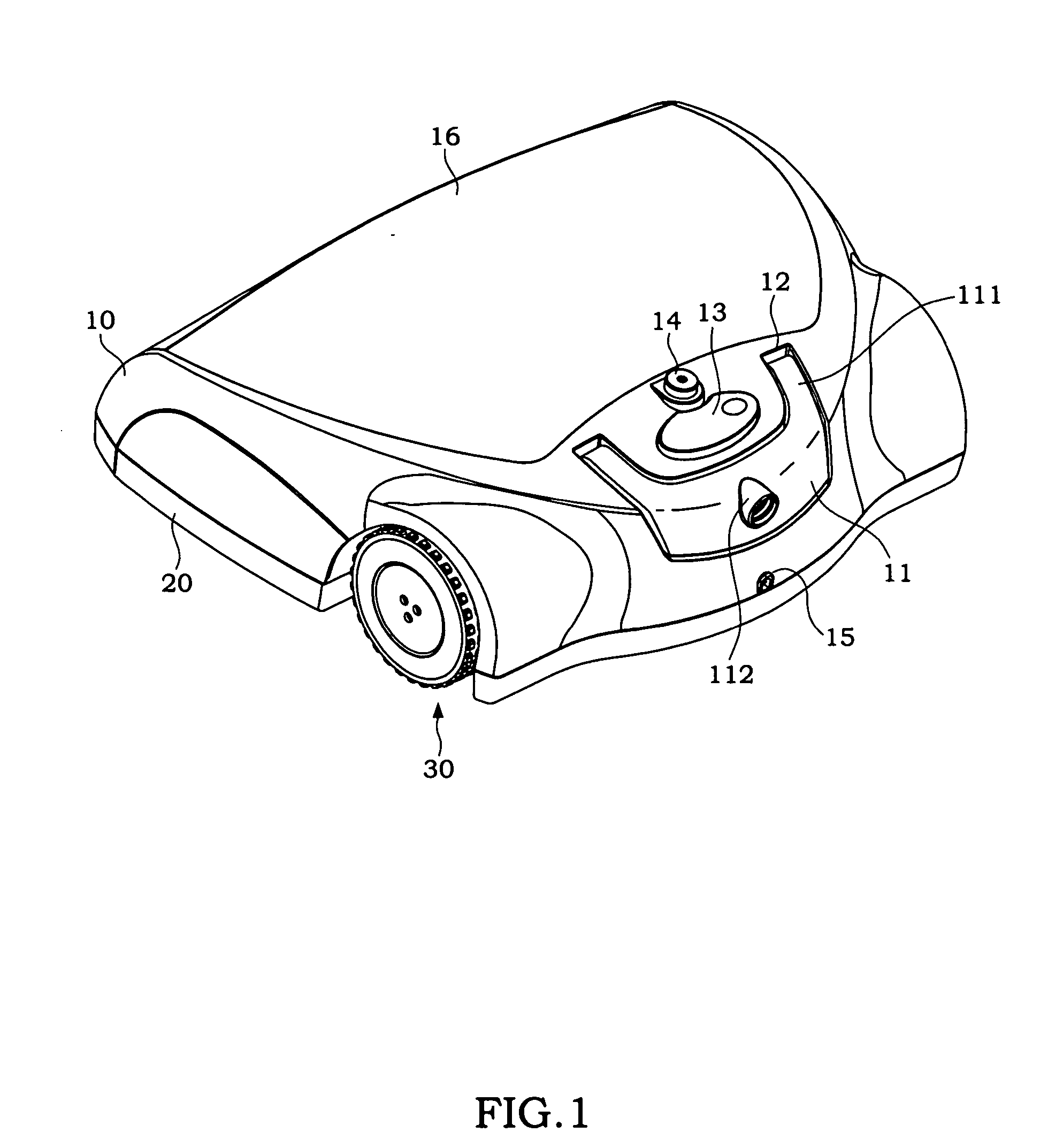
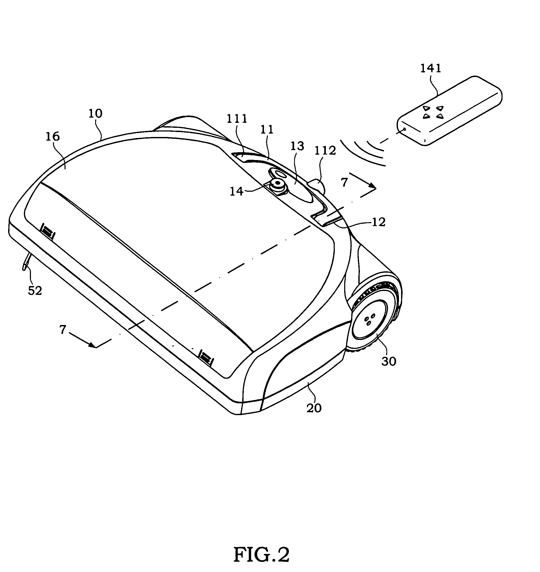
[0029] Referring to FIGS. 1 and 2 respectively for the rear view and front view of the remote control sweeper in accordance with the present invention, the sweeper comprises an upper casing 10 and a lower casing 20 being engaged with each other, and the left and right sections of the upper and lower casings 10, 20 separately install a wheel 30, 30′. The upper casing 10 pivotally connects a pushing section 11 at its surface, and the pushing section 11 can be turned to any angle with respect to the pivotal end 111 as the center, and can be placed flatly and accommodated into a groove 12 of the upper casing 10. Further, the upper casing 10 further comprises a power button 13 and a remote control receiver 14, and a cover 16 for covering an upper casing opening 161 can be installed and detached easily. In FIG. 1, the upper casing 10 further comprises a power socket 15.

[0030] Referring to FIGS. 3 and 4, we can see that the upper casing 10 comes with a specific accommodating space, after ...


PUM


Abstract

A remote control sweeper includes a wireless remote control receiver installed at the sweeper; a remote control for transmitting a direction control signal to the remote control receiver via a wireless transmission to control the moving direction of the sweeper, such that the sweeper can be moved to automatically clean up the dirt and collect the dust on a floor.

Description

BACKGROUND OF THE INVENTION [0001] 1. Field of the Invention [0002] The present invention generally relates to a cleaning machine, and more particularly to a sweeper whose moving direction can be controlled by a remote control. [0003] 2. Description of the Related Art [0004] The common tool used for sweeping floor is a broom, which can be used to clean up a small area of floor, but using a broom to clean up a large area of floor is very inefficient. To save efforts of the cleaning job, an electric sweeper is introduced, so that users can push and control the electric sweeper to automatically clean up and collect the dirt on the floor along the path where the sweeper passes. [0005] Regardless of the traditional broom and electric sweeper, the inventor of the present invention believe that pushing the machine by users is difficult, particularly for a person who has a walking problem. Even for general users, operating or pushing the machine will cause backaches easily. Furthermore, the...

Claims


Application Information

Patent Timeline
Patent Type & Authority Applications(United States)
IPC IPC(8): A47L11/24
CPCA47L11/32A47L2201/00A47L11/4011A47L11/33
Inventor CHENG, TZO FANGCHANG, YONG-HAN
Owner GUTEN ELECTRONICS IND
Why Eureka
Try Eureka