Torque limiting device

a technology of torque limiter and torque limiter, which is applied in the direction of wrenches, medical science, surgery, etc., can solve the problems of tool breaking or fracture, tool bending or bending, and serious injuries

Inactive Publication Date: 2007-01-11
KYPHON
View PDF94 Cites 123 Cited by
  • Summary
  • Abstract
  • Description
  • Claims
  • Application Information

AI Technical Summary

Benefits of technology

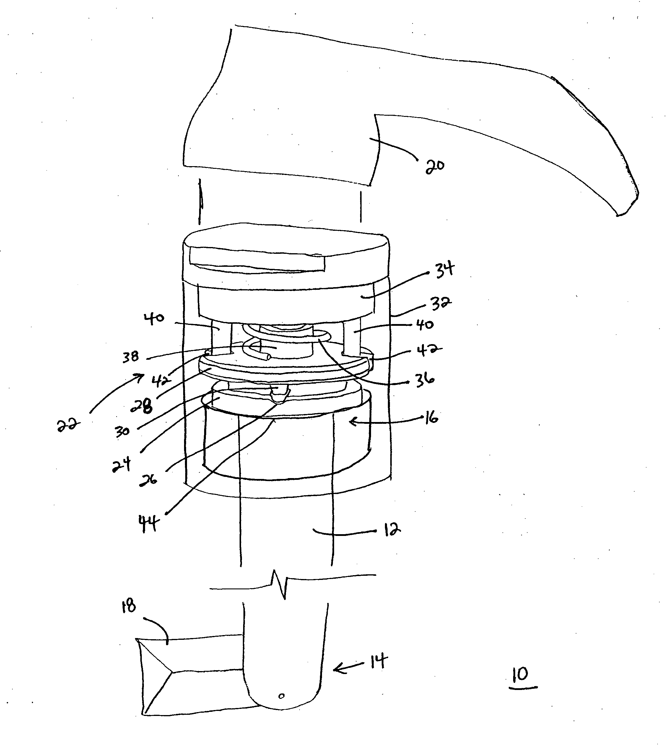
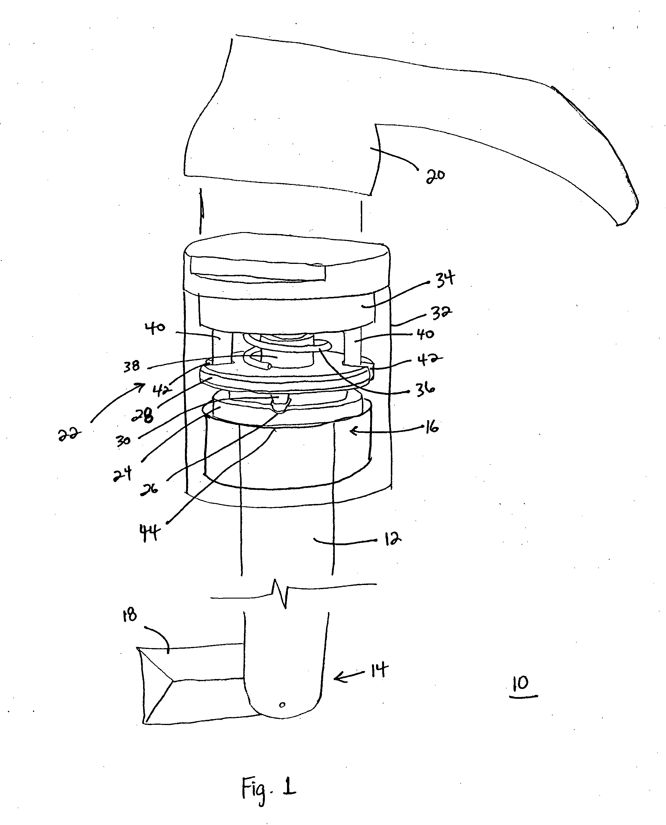
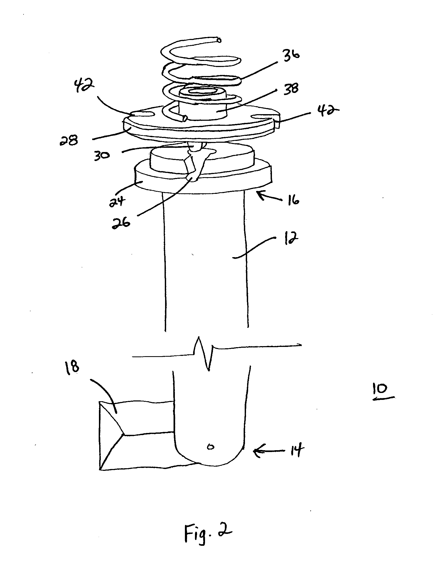
[0014] A surgical tool, such as a curette, with a torque limiting device of the present invention, limits the torque applied to the tip of the tool to reduce the possibility of damaging the tool. In addition, the torque limiting device of the present invention may be reengaged so that the tool may be used again immediately after disengagement.
[0016] Accordingly, in some embodiments, the present invention provides a surgical tool that limits torque applied to the surgical implement without permanently deforming or damaging the tool. Therefore, if a surgeon applies too high a torque to the handle of the tool, the tool will disengage without permanently damaging the tool. In addition, the tool may be reengaged so that the surgeon may continue the surgery without delay.
[0018] A tool, and / or a surgical tool, of the present invention may be used in a manner similar to prior tools and provide the added benefit of being re-settable and thus reusable if a predetermined torque is exceeded. Thus, in some embodiments, a method of the present invention comprises applying a torque to a tool comprising a torque limiting device of the present invention wherein if a predetermined torque is exceeded by an excess torque causing the first and second planar surfaces to rotate independently from each other, the method comprises applying a rotational force to the first planar surface in a direction substantially opposite the direction of the excess torque to re-engage the first and second planar surfaces and cause a rotational force applied to the first planar surface to be transmitted to the second planar surface.

Problems solved by technology

Tools, such as medical tools, may undergo relatively high torque forces.
If the torque force is greater than the tool can withstand, the tool may break or fracture.
Tool breakage can lead to serious injuries.
For example, if a medical tool breaks while still inserted in a patient, the patient may suffer serious injuries.
Although this prior design may be effective for reducing injuries, it is costly as once the tool is broken it may be useless and therefore replaced.
Furthermore, this prior design is inconvenient because when the tool breaks, work must be stopped and restarted with a new tool.

Method used


Image

  • Torque limiting device
  • Torque limiting device
  • Torque limiting device

Examples


Embodiment Construction

[0027] For the purposes of this specification, unless otherwise indicated, all numbers expressing quantities, conditions, and so forth used in the specification are to be understood as being modified in all instances by the term “about.” Accordingly, unless indicated to the contrary, the numerical parameters set forth in the following specification are approximations that can vary depending upon the desired properties sought to be obtained by the present invention. At the very least, and not as an attempt to limit the application of the doctrine of equivalents to the scope of the claims, each numerical parameter should at least be construed in light of the number of reported significant digits and by applying ordinary rounding techniques.

[0028] Notwithstanding that the numerical ranges and parameters setting forth the broad scope of the invention are approximations, the numerical values set forth in the specific examples are reported as precisely as possible. Any numerical value, h...


PUM


Abstract

Torque limiting devices, tools comprising torque limiting devices and methods for using torque limiting devices are disclosed. In an embodiment, a torque limiting device comprises a first and a second surface disposed in substantially adjacent parallel planar relationship such that within a predetermined torque range the first and second surface rotate together such than a torque applied to the first surface is translated to the second surface. When the torque applied exceeds a certain critical torque, the first and second surfaces slip and therefore the excessive torque is not transferred.

Description

FIELD OF THE INVENTION [0001] The present invention relates to mechanical devices. Embodiments of the present invention include torque limiting devices, tools comprising torque limiting devices, methods for using torque limiting devices and medical kits comprising torque limiting devices. BACKGROUND [0002] Tools, such as medical tools, may undergo relatively high torque forces. If the torque force is greater than the tool can withstand, the tool may break or fracture. Tool breakage can lead to serious injuries. For example, if a medical tool breaks while still inserted in a patient, the patient may suffer serious injuries. Therefore, it is desirable to design tools such that injury inducing breakage is minimized or eliminated. [0003] In order to avoid injury inducing breakage past tools have been designed to break in a predetermined position when torque forces are greater than the tool can withstand. For example, a groove can be cut such that a predetermined torque causes the tool t...

Claims


Application Information

Patent Timeline
Patent Type & Authority Applications(United States)
IPC IPC(8): B25B23/157
CPCA61B17/8875B25B23/1427A61C1/186A61B2019/301A61B2090/031A61C1/18B25B23/14
Inventor PHAN, CHRISTOPHER U.
Owner KYPHON
Why Eureka
Try Eureka