Inking device of printing press

a printing press and inking technology, applied in printing presses, printing press parts, printing, etc., can solve the problems of inability to increase printing accuracy, difficult fine adjustment, and large loss of adjusting time and test printing sheets, and achieve the effect of easy setting

Inactive Publication Date: 2007-01-11
KOMORI CORP
View PDF10 Cites 20 Cited by
  • Summary
  • Abstract
  • Description
  • Claims
  • Application Information

AI Technical Summary

Benefits of technology

[0022] According to the inking device of the printing press concerned with the present invention, the ink ductor roller is supported between a pair of the swing members with no lateral clearance being provided, and the swing members are moved in the axial direction of the ink ductor roller by the moving means. By so doing, the ink ductor roller can be easily set at the home position, and the ink ductor roller is laterally moved even during operation of the machine to achieve its position adjustment.

Problems solved by technology

However, the above-mentioned adjusting work for the ink ductor roller has posed the following problems:
Such operations repeated several times result in great losses of the adjusting time and test printing sheets.
(2) Since the adjusting work for the ink ductor roller is done manually, fine adjustment is difficult and printing accuracy cannot be increased.
(3) When initially setting the ink ductor roller, it is difficult to know where in the clearances of the split clamping holders the ink ductor roller is located, and it is hard to determine the home position.
Thus, whenever printing is changed, the ink ductor roller has to be replaced, requiring frequent adjusting work for the ink ductor roller.

Method used


Image

  • Inking device of printing press
  • Inking device of printing press
  • Inking device of printing press

Examples


embodiment 1

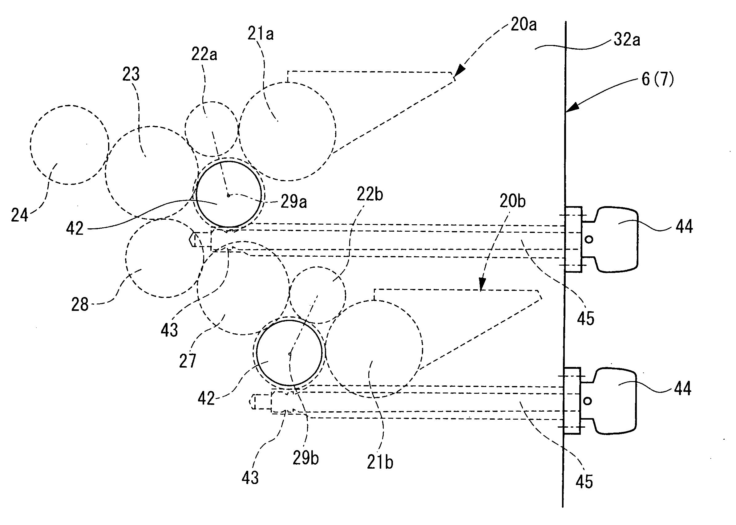
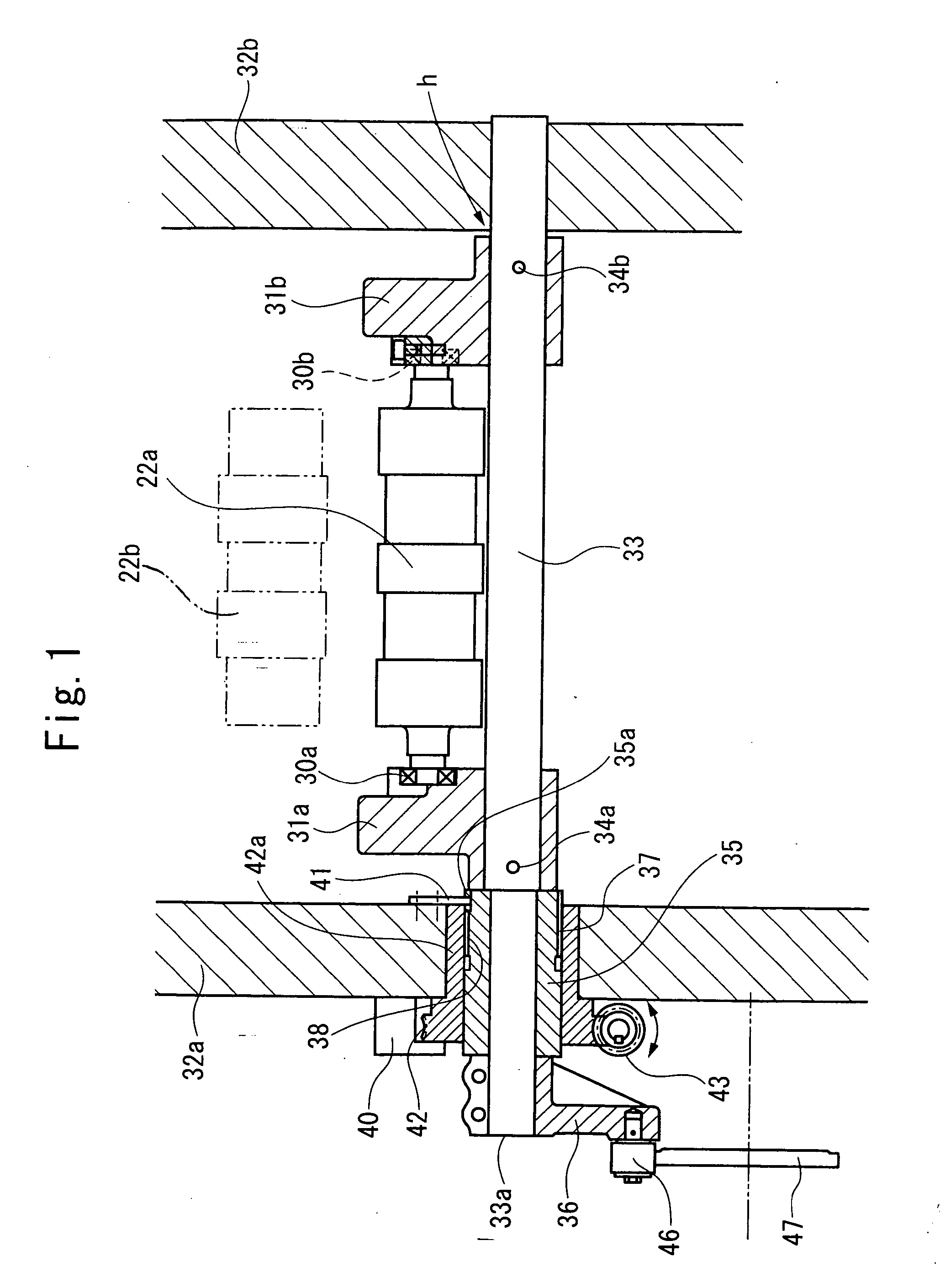
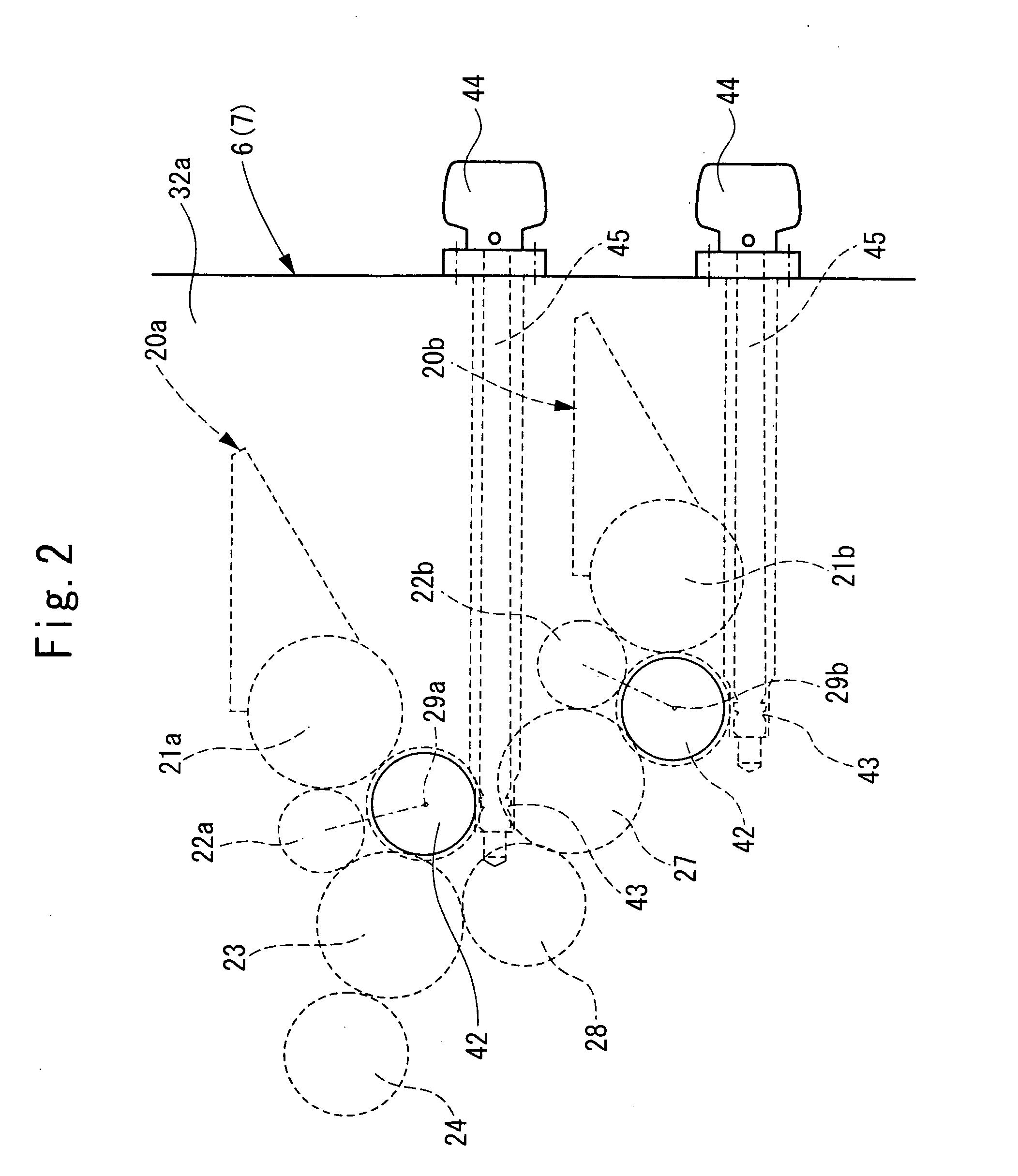
[0032]FIG. 1 is a support configuration drawing of an ink ductor roller, showing Embodiment 1 of the present invention. FIG. 2 is an essential configuration drawing of an inking unit. FIG. 3 is a side view of a four-color perfecting offset press.

[0033] In a printing unit 1 of the present printing press, as shown in FIG. 3, a blanketed impression cylinder 2 equipped with a sheet gripper device and a blanket cylinder 3 without a sheet gripper device are supported nearly horizontally, and their circumferential surfaces are in contact with each other.

[0034] Four plate cylinders 4 are arranged on the circumferential surface of the blanketed impression cylinder 2, and four plate cylinders 5 are arranged on the circumferential surface of the blanket cylinder 3. Inking units 6, 7 are movably provided to be movable toward and away from these plate cylinders 4, 5, and can supply ink and water while contacting the plate cylinders 4, 5.

[0035] A delivery cylinder 9 of a delivery unit 8 is dis...

embodiment 2

[0053]FIG. 4 is an essential configuration drawing of an inking unit, showing Embodiment 2 of the present invention. FIG. 5 is a configuration drawing of a motor drive portion.

[0054] This is an embodiment in which the worm shaft 43 in Embodiment 1 is rotationally driven by a motor 53 instead of by the operating shaft 45 having the dial-equipped handle 44, and the amount of rotation of the bearing portion 42a integral with the worm wheel 42 (i.e., the amount of movement of the ink ductor rollers 22a, 22b) is detected by a potentiometer 52 via gears 50, 51. Other features are the same as those in Embodiment 1, and thus duplicate explanations are omitted, with the same members as those in FIG. 1 being assigned the same numerals as those in FIG. 1.

[0055] According to the above-described configuration, the advantage that the position adjustment of the ink ductor rollers 22a, 22b can be made automatically and by remote control is obtained, in addition to the same actions and effects as ...

embodiment 3

[0056]FIG. 6 is an essential configuration drawing of an inking unit, showing Embodiment 3 of the present invention.

[0057] This is an embodiment in which the worm shaft 43 in Embodiments 1 and 2 is built in the frame 32a to achieve the compact configuration of the machine. Other features are the same as those in Embodiment 1, and thus duplicate explanations are omitted, with the same members as those in FIGS. 1 and 4 being assigned the same numerals as those in FIGS. 1 and 4.


PUM


Abstract

An inking device of a printing press, including an ink ductor roller reciprocating between a receipt position, at which the ink ductor roller contacts an ink fountain roller to receive ink, and a transfer position, at which the ink ductor roller contacts an ink distribution roller or a first intermediate roller located downstream in an ink transfer direction to pass the ink on to the roller, comprises: a pair of split clamping holders supporting the ink ductor roller and supported swingably; and moving means, comprising a shaft, a sleeve, a bearing portion, a worm wheel, a worm shaft, and an operating shaft having a dial-equipped handle, for moving the pair of split clamping holders in the axial direction of the ink ductor roller.

Description

BACKGROUND OF THE INVENTION [0001] 1. Field of the Invention [0002] This invention relates to an inking device of a printing press and, more particularly, to an inking device of a printing press preferred for rainbow printing. [0003] 2. Description of the Related Art [0004] A rainbow printing press is disclosed, for example, in Japanese Patent Application Laid-Open No. 2001-310447. It is a rainbow printing press of a so-called double duct type, in which ink is flowed only on projections of each of upper and lower ink ductor rollers having the projections and depressions on their roller surfaces, and inks flowed on these projections are merged by an ink merger (distribution) roller to carry out rainbow printing. [0005] Thus, lateral alignment between the upper and lower ink ductor rollers is important, and lateral alignment of the projections of the upper and lower ink ductor rollers with plate cylinders (plate surfaces) is also important. [0006] In performing adjusting work for this...

Claims


Application Information

Patent Timeline
Patent Type & Authority Applications(United States)
IPC IPC(8): B41F31/00
CPCB41F31/14
Inventor KUSAKA, AKEHIRO
Owner KOMORI CORP
Why Eureka
Try Eureka