
Compound paper making fabric

a paper fabric and fabric technology, applied in the field of compound paper making fabrics, can solve problems such as paper sheet markings, and achieve the effects of less marking, improved paper sheet smoothness, and improved paper contact side smoothness

Inactive Publication Date: 2007-01-11
VOITH PATENT GMBH
View PDF5 Cites 17 Cited by
  • Summary
  • Abstract
  • Description
  • Claims
  • Application Information

AI Technical Summary

Benefits of technology

[0007] The present invention is directed towards providing a paper making fabric, especially a forming fabric, having improved smoothness of the paper contacting side leading to improved, and therefore less marking, of the paper sheet.
[0009] Additionally, according to the present invention the number of crossing points is reduced to create an optimum balance to fulfil the requirement of achieving good binding between the paper side and the wear side fabric, thereby achieving as the least possible crossing points that destroy the planarity of the paper contacting surface as well as leading to hydraulic marking on the paper sheet caused by the disturbance of the regular inner structure of the fabric. By further providing a ratio of paper side threads to wear side threads, both weaving with the binding threads and being greater than or equal to 1.0, the planarity and smoothness of the paper contacting surface can be improved. leading to a paper contacting surface having less tendency for marking the paper sheet compared to those from prior art fabrics.
[0012] According to a preferred embodiment of the present invention the diameter of the paper side threads is less than the diameter of the wear side threads. The use of thicker yarns on the wear side compared to the yarns on the paper side leads to a fabric having a planar and smooth paper contacting surface and having a high wear resistance.

Problems solved by technology

The structure has a high number of crossing points each of which destroys the planarity of the paper contacting side of the paper side fabric resulting in markings of the paper sheet.

Method used


Image

  • Compound paper making fabric
  • Compound paper making fabric
  • Compound paper making fabric

Examples


Embodiment Construction

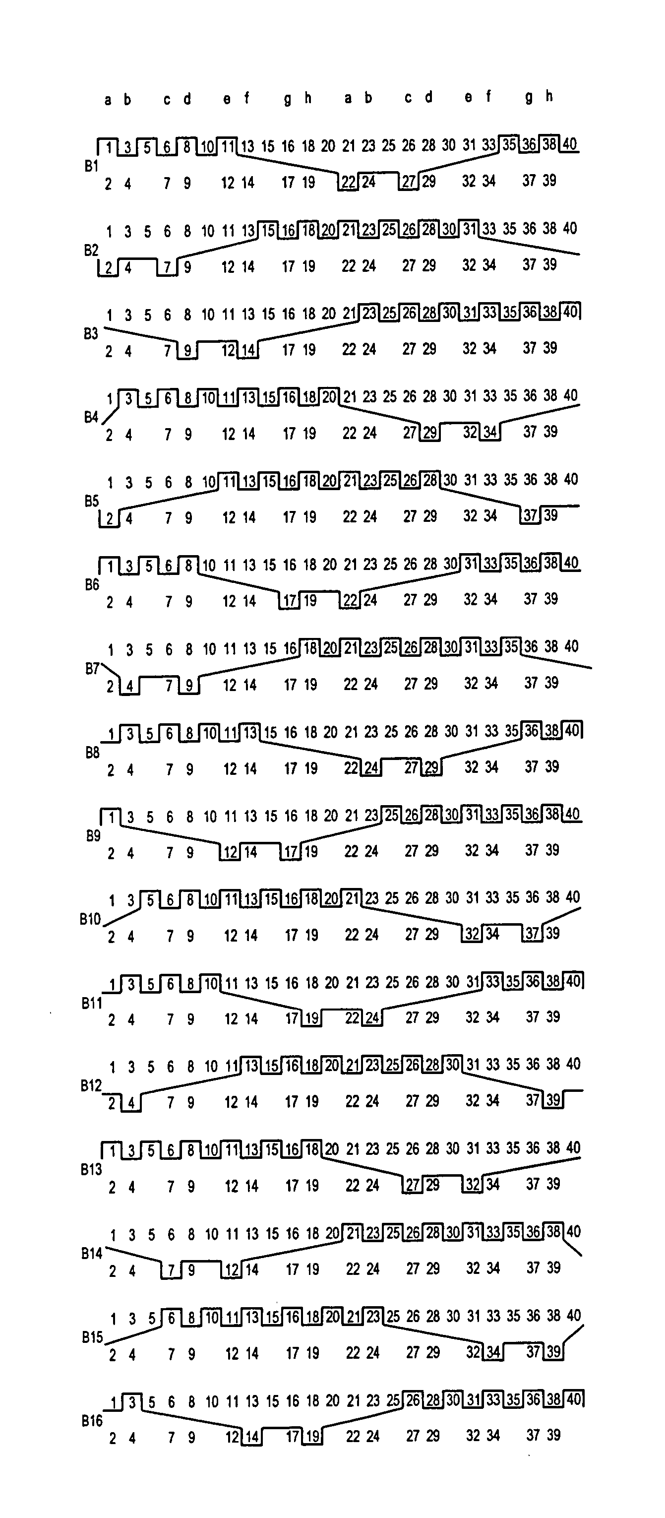
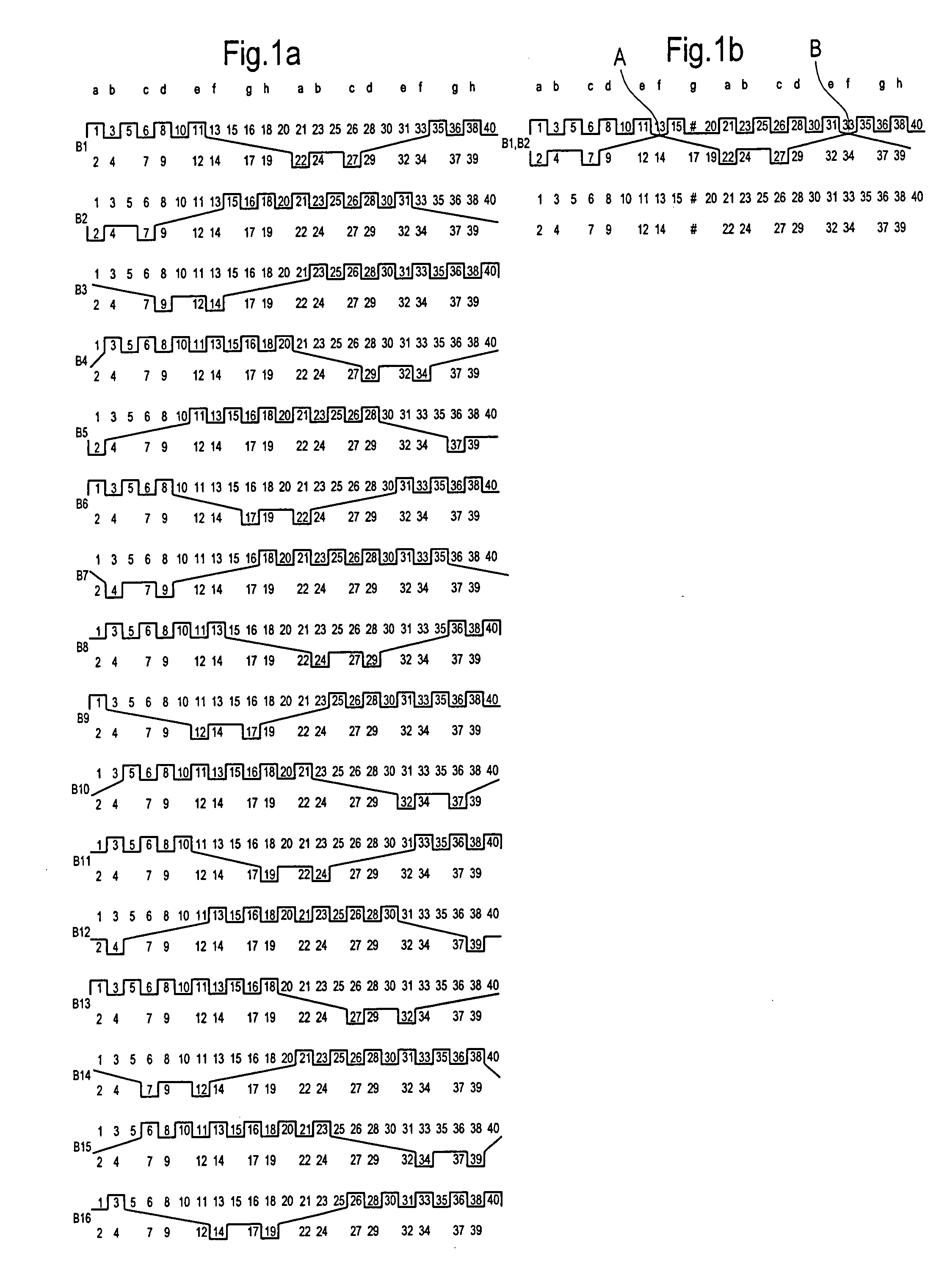
[0019]FIG. 1a shows the weave paths of 16 consecutive binding threads B1 to B16 forming the full weave repeat by weaving with paper side weft threads 1, 3, 5, 6, 8, 10, 11, 13, 15, 16, 18, 20, 21, 23, 25, 26, 28, 30, 31, 33, 35, 36, 38 and 40 and by weaving with wear side threads 2, 4, 7, 9, 12, 14, 17, 19, 22, 24, 27, 29, 32, 34, 37 and 39.

[0020] The binding threads are arranged in pairs, for example, pair B1,B2; pair B3,B4 etc., such that each pair together weaves a full weave path on the paper side and on the wear side. By doing this the binding threads alternate from weaving with the paper side threads to weave with the wear side threads and vice versa, thereby crossing each other by forming two different types of crossing points A and B. This is best illustrated in FIG. 1B.

[0021] The weave pattern of the wear side is formed by wear side repeat units a through h having eight wear side threads. The weave pattern on the paper side is a linen binding weave pattern.

[0022] The emb...


PUM


Abstract

The invention relates to a forming fabric, with a paper side fabric having paper side threads and with a wear side fabric having wear side threads. The paper side fabric and the wear side fabric are superimposed to one another and connected by binding threads weaving with both the paper side threads and the wear side threads, both extending in cross direction relative to the binding threads. The binding threads form part of the weave pattern of the paper side fabric and form part of the weave pattern of the wear side fabric, and alternate from weaving with the paper side fabric to weave with the wear side fabric and vice versa, thereby crossing each other forming crossing points. The wear side weave pattern is repeated by wear side repeat units, wherein the binding threads alternate such that one or less than one crossing point within each wear side weave repeat unit is formed and the ratio of the paper side threads to the wear side threads is greater than 1.

Description

BACKGROUND OF THE INVENTION [0001] 1. Field of the Invention [0002] The present invention relates to compound paper making fabrics, especially to forming fabrics, for use in a paper machine to manufacture a fibrous web. [0003] 2. Discussion of Background Information [0004] Various styles of paper making fabrics, especially forming fabrics are known in the art. [0005] EP 1 294 981 discloses a compound forming fabric for use in the forming section of a paper making machine comprising a paper side fabric and a wear side fabric being bound together by pairs of binding threads forming part of the weave pattern of the paper side fabric and part of the weave pattern of the wear side fabric and alternate from weaving with the paper side fabric to weave with the wear side fabric and vice versa, thereby crossing each other by forming crossing points. The forming fabric according to EP 1 294 981 shows per wear side weave repeat two crossing points. The structure has a high number of crossing p...

Claims


Application Information

Patent Timeline
IPC IPC(8): D03D23/00
CPCD21F1/0045Y10S162/903
Inventor QUIGLEY, SCOTTRINGER, MARTIN
Owner VOITH PATENT GMBH
Learn More