Elastic support device and power steering device

a technology of elastic support and power steering, which is applied in the direction of mechanical devices, shock absorbers, transportation and packaging, etc., can solve the problems of low cost, and achieve the effect of reducing vibration and noise in the vehicle body, sufficient vibration absorption, and low cos

Inactive Publication Date: 2007-01-11
JTEKT CORP
View PDF27 Cites 11 Cited by
  • Summary
  • Abstract
  • Description
  • Claims
  • Application Information

AI Technical Summary

Benefits of technology

[0008] According to this mode, it is possible to satisfactorily make the elastic member flex by forming the recess and to sufficiently absorb vibration from the vibration transmission medium. Consequently, vibration and noise in a vehicle body can be significantly reduced by restraining the transmission of the vibration to the vehicle body through the fixing member. Further, the elastic member may be only provided with the recess, resulting in low cost.
[0009] Since the body of the elastic member is fastened to the sleeve, the body of the elastic member can be prevented from being scraped against and separated from the sleeve by the vibration from the vibration transmission medium, for example. Consequently, the elastic member can be prevented from being damaged and slipping off the sleeve, so that a vibration absorbing effect can be satisfactorily maintained for a long time period.

Problems solved by technology

Further, the elastic member may be only provided with the recess, resulting in low cost.

Method used


Image

  • Elastic support device and power steering device
  • Elastic support device and power steering device
  • Elastic support device and power steering device

Examples


Embodiment Construction

[0013] A preferred embodiment of the present invention will be described while referring to the accompanying drawings.

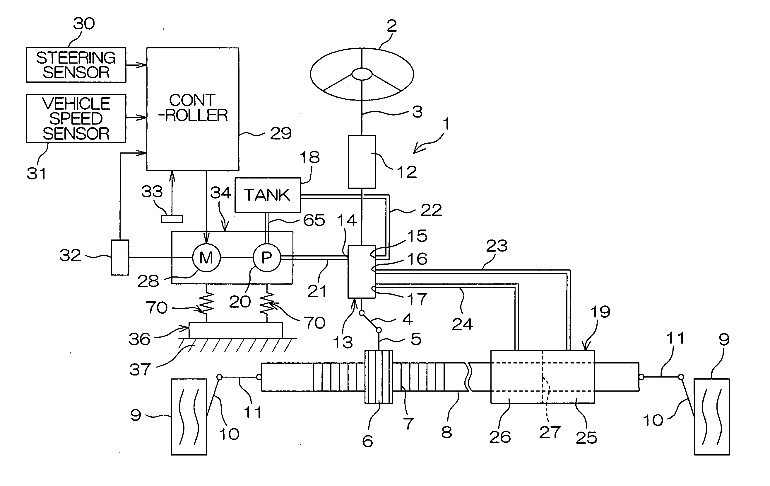
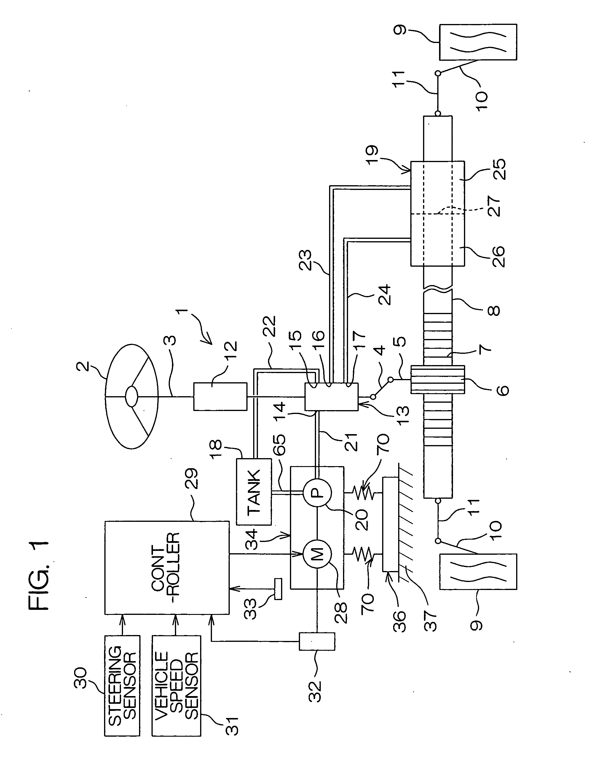
[0014]FIG. 1 is a schematic view showing the schematic configuration of a power steering apparatus 1 according to an embodiment of the present invention. Referring to FIG. 1, the power steering apparatus 1 comprises a steering member 2 such as a steering wheel operated by a driver, a steering shaft 3 connected to the steering member 2, a pinion shaft 5 connected to the steering shaft 3 through an intermediate shaft 4, and a rack shaft 8 having a rack 7 meshed with a pinion 6 provided in the pinion shaft 5 and extending along the width of a vehicle.

[0015] To a pair of ends of the rack shaft 8, knuckle arms 10 for supporting corresponding wheels 9 are respectively connected through corresponding tie rods 11. By the above-mentioned configuration, when the steering member 2 is operated so that the steering shaft 3 is rotated, the rotation is transmitted to the pinion s...


PUM


Abstract

An elastic support device (70) has a vibration reduction member (35) for supporting a vibration transmission medium (34). The vibration transmission medium (34) is connected to the vibration reduction member (35) by a connection member (42). The vibration reduction member (35) includes a sleeve (43) made from a rigid body, through which sleeve the connection member (42) is inserted, and an elastic member (45) surrounding an outer periphery of the sleeve (43). The elastic member (45) includes a tubular body (49) firmly fixed on an outer peripheral surface (44) of the sleeve (43) and an annular plate portion (50) projecting radially outward of the body (49). A fitting groove (58) of an outer peripheral edge portion (57) of the annular plate portion (50) is fitted on a peripheral edge (60) of an installation hole (59). A first and a second face (52, 53) of the annular plate portion (50) include recesses (54, 55), respectively. In the annular plate portion (50), a thin-walled portion (56) corresponding to a portion between bottoms of the recesses (54, 55) of the first and the second faces (52, 53) is formed.

Description

TECHNICAL FIELD [0001] The present invention relates to an elastic support device and a power steering apparatus. BACKGROUND ART [0002] Automobiles comprise various types of devices such as engines and steering devices, and the devices include devices mounted on the vehicle bodies (bodies) with brackets serving as mounting members sandwiched therebetween. [0003] For example, an automobile disclosed in Japanese Unexamined Patent Publication No. 11-334616, A laid open to public inspection with non-examination by Japanese Patent Office on Dec. 7, 1999 comprises an electric motor-driven pump type power steering apparatus. The electric motor-driven pump type power steering apparatus drives a pump using an electric motor, and supplies hydraulic oil stored in a tank or the like to a power cylinder coupled to a steering mechanism to produce a steering assist force. The electric motor, the pump, the tank, and the like are mounted on a vehicle body with a fixing member sandwiched therebetween...

Claims


Application Information

Patent Timeline
Patent Type & Authority Applications(United States)
IPC IPC(8): B62D5/06F16F7/00F16F1/373B62D5/07F16F15/08
CPCF16F15/08F16F1/3732
Inventor HAMASAKI, YOSHIAKIYOSHIHARA, YOSHIHITOTANIWA, TAKASHI
Owner JTEKT CORP
Why Eureka
Try Eureka