Display panel mount bracket

a technology for mounting brackets and display panels, applied in the field of support, can solve problems such as design stability and safety, and achieve the effect of increasing friction and effective improving market compatibility

Inactive Publication Date: 2007-01-11
SALLAS INDAL
View PDF10 Cites 38 Cited by
  • Summary
  • Abstract
  • Description
  • Claims
  • Application Information

AI Technical Summary

Benefits of technology

[0009] It is a primary object of the present invention to provide a display panel mount bracket to adjust the spaced distance properly according to conditions of a wall by each support shaft and cooperate with the stepless fixed board and adapting base to be suitable for displays with various types and specs to further effectively improve the market compatibility.
[0010] It is a secondary object of the present invention to provide a display panel mount bracket with a first spacing slot for matching with the activation device and a second spacing slot for matching with the support shaft dug on each swin

Problems solved by technology

For the whole, the design la

Method used


Image

  • Display panel mount bracket
  • Display panel mount bracket
  • Display panel mount bracket

Examples


Embodiment Construction

[0018] The structural features and the effects to be achieved may further be understood and appreciated by reference to the presently preferred embodiments together with the detailed description.

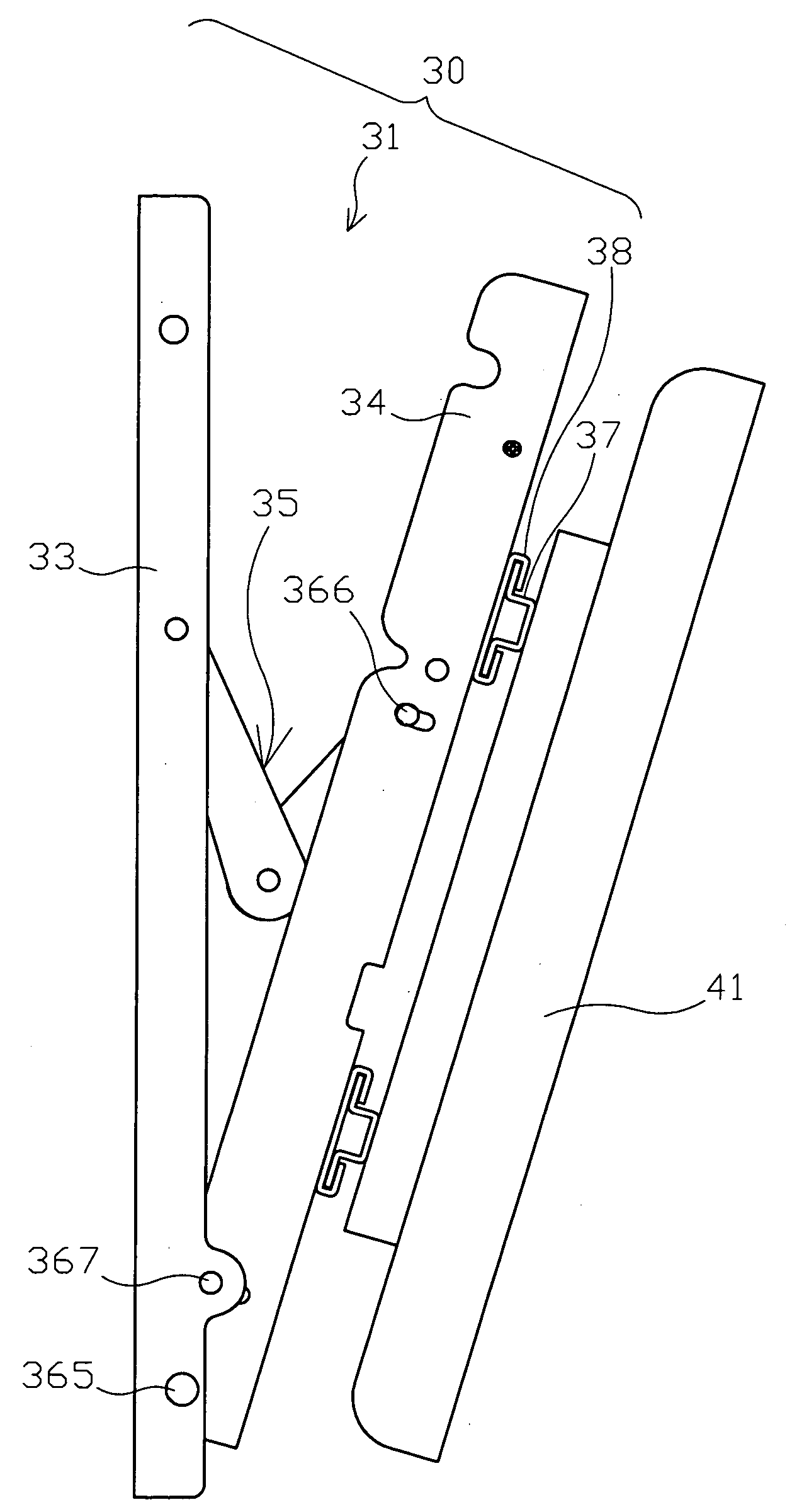
[0019] Firstly, please simultaneously refer to FIG. 3A and FIG. 3B, respectively a three-D exploded diagram and a three-D combination diagram of a preferred embodiment of the present invention. As shown, the main structure of the display panel mount bracket 30 of the present invention comprises: at least one angle adjustment set 31 each of which comprises a support shaft 33 pivoting with a swing shaft 23 and an activation device 35, a plurality of first support holes 331 dug on the support shaft 33, and a plurality of first swing holes 341 dug on the swing shaft 34; at least one fixed board (37 denoted in FIG. 4) on each of which a raised bar 371 is protruded, and a plurality of fixed holes 372 dug on the raised bars 371 for matching with a display 41; at least one adapting base 38 a face o...


PUM


Abstract

A display panel mount bracket comprises at least one angle adjustment set, at least one fixed board, and at least one adapting base. Among them, each angle adjustment set comprises a support shaft pivoting with a swing shaft and an activation device for adjusting the sandwiched angle mounted between the swing shaft and the support shaft. A plurality of fixed holes for matching with a display set on the fixed board, and each adapting base is linked with the fixed board and has a hanging button for matching with the first swing holes. Further, each support shaft can be latched on a wall. This way, spaces between each angle adjustment set can be mobile adjusted without limiting by conditions of the wall, as well as the sandwiched angle of the display and the wall can be adjusted by a stepless way to provide users an optimum angle of view.

Description

FIELD OF THE INVENTION [0001] The present invention is related to a support and more particularly to a display panel mount bracket. Spaces between each angle adjustment set can be mobile adjusted without limiting by conditions of the wall, as well as the sandwiched angle of the display and the wall can be adjusted by a stepless way to provide users an optimum angle of view. BACKGROUND [0002] By the vigorous development of electronic technology, the manufacturing technology of thin display is also increasingly mature and gradually replaces traditional CRT displays. Furthermore, thickness of frames thereof is lighter and thinner than the traditional CRT displays, it thus becomes one of decorations in living lives. The arranged position relates to visual effect of indoor arrangements. However, in addition to the decorating effect, an angle of pitch thereof is also an important subject. By the difference of heights and posture habits of users, there are different optimum angles of views...

Claims


Application Information

Patent Timeline
IPC IPC(8): E04G3/00
CPCF16M13/02F16M11/10
Inventor WANG, CHIA-MING
Owner SALLAS INDAL
Why Eureka
Try Eureka