Brushless generator having coreless assembly

a brushless, generator technology, applied in the direction of dynamo-electric machines, magnetic circuit rotating parts, magnetic circuit shapes/forms/construction, etc., can solve the problems of prior art not fulfilling users' requests for actual use, iron loss and mechanical loss, etc., to achieve high rotation speed, no iron loss, and high usage efficiency

Active Publication Date: 2007-01-11
YANGDA
View PDF7 Cites 72 Cited by
  • Summary
  • Abstract
  • Description
  • Claims
  • Application Information

AI Technical Summary

Benefits of technology

[0004] Therefore, the main purpose of the present invention is to obtain a high rotation speed, a high usage efficiency, no iron loss and a small mechanical loss while increasing the output efficiency of electricity by using a speed-up device.

Problems solved by technology

Although the generator of the prior art can generate electric power, some iron loss and mechanical loss may occur owing to the brush and the core in it with more complex structure.
So, the prior art does not fulfill users' requests on actual use.

Method used


Image

  • Brushless generator having coreless assembly
  • Brushless generator having coreless assembly
  • Brushless generator having coreless assembly

Examples


Embodiment Construction

[0011] The following descriptions of the preferred embodiments are provided to understand the features and the structures of the present invention.

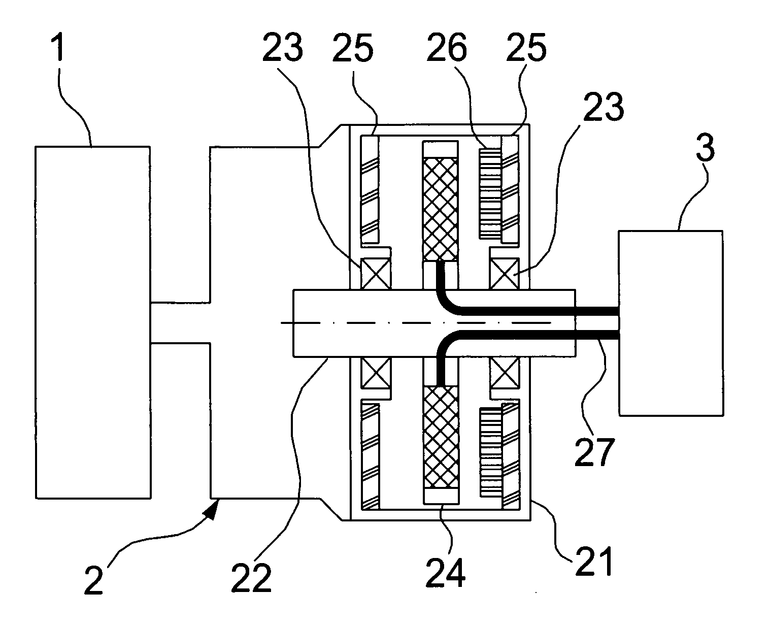
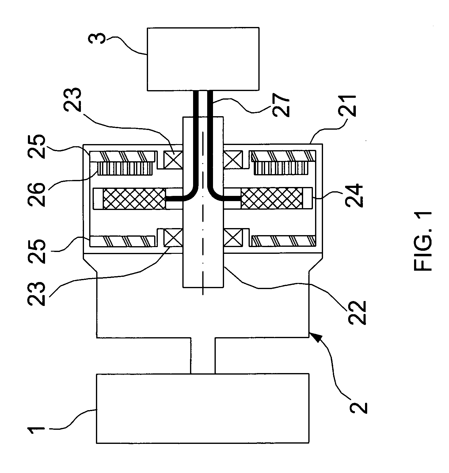
[0012] Please refer to FIG. 1, which is a cross-sectional view showing a first preferred embodiment according to the present invention. As shown in the figure, the present invention is a brushless generator having coreless assembly, comprising an actuator 1, a power generator head 2 and a voltage stabilizer 3, where the generator has a high rotation speed, a high usage efficiency, no iron loss and a small mechanical loss.

[0013] The actuator 1 can be a mechanical engine power, a natural wind force, a water force, an animal power, etc.

[0014] The power generator head 2 comprises a case 21 connected with the actuator 1. A first shaft 22 is flexibly penetrated through center of the case 21. A bearing 23 is correspondingly located between the case 21 and each of two opposite ends of the first shaft 22. A coreless wound stator 24 is deposed o...


PUM


Abstract

A brushless generator has a high rotation speed, a high usage efficiency, no iron loss and a small mechanical loss while the electric power output of the generator is increased

Description

FIELD OF THE INVENTION [0001] The present invention relates to a brushless generator; more particularly, relates to obtaining a high rotation speed, a high usage efficiency, no iron loss and a small mechanical loss while increasing the output efficiency of electricity. DESCRIPTION OF THE RELATED ART(S) [0002] A generator of a prior art is disclosed in Taiwan, as shown in FIG. 4, comprises a fixed shell 6, a rotating shaft 61, a rotating inner shell 62, a transmission gear set 63, a rotor 64 and a coil ring 65, where the fixed shell 6 has a cylinder shape; two bearing holes are set correspondingly at two ends of the fixed shell 6; a default generator ouput set is deposed in an end of the fixed shell 6; two ends of the rotating shaft 61 are correspondingly pivoted on the bearing holes of the fixed shell 6; an end of the rotating shaft 61 is an input end; the rotating inner shell 62 are pivoted inside the fixed shell 6 with bearing holes to be pivoted on the rotating shaft 61; an inner...

Claims


Application Information

Patent Timeline
Patent Type & Authority Applications(United States)
IPC IPC(8): H02K7/10H02K21/12H02K1/22
CPCH02K21/24H02K7/1807
Inventor LIN, MIN-HUANG
Owner YANGDA
Why Eureka
Try Eureka