Vehicle mounted radar apparatus

a vehicle-mounted radar and electromagnetic scanning technology, which is applied in the direction of using reradiation, measuring devices, instruments, etc., can solve the problems of inability to detect reflected waves, limited distance range where targets can be detected, and vehicle-mounted radar apparatus catches more unnecessary reflected waves (non-desired waves)

Inactive Publication Date: 2007-01-11
DENSO IT LAB +1
View PDF17 Cites 21 Cited by
  • Summary
  • Abstract
  • Description
  • Claims
  • Application Information

AI Technical Summary

Benefits of technology

[0028] According to this aspect of the invention, the advancing direction of ones own vehicle is computed in such a way that the information on road facility is obtained on the basis of the already obtained search signals of the radar, and the curvature of the road is computed from the information, so that the advancing direction of ones own vehicle can be easily computed without a specific unit for obtaining the advancing direction of ones own vehicle, such as a car navigation unit.

Problems solved by technology

If the reflected wave is widely attenuated and the signal level of the reflected wave is lower than the noise level of a system, it is impossible to detect the reflected wave.
Then, the distance range where targets can be detected is limited.
Besides, it is predicted that the vehicle-mounted radar apparatus catches more unnecessary reflected waves (non-desired waves) which are reflected from targets excluding the vehicle traveling lane although the range which is subject for detection is vehicle traveling lane, such as a road.
This leads to deterioration of the detection accuracy of the target which exists in the range to be detected.
For this reason, it is difficult to detect the target on the range where vehicles run which is far from the radar apparatus.

Method used


Image

  • Vehicle mounted radar apparatus
  • Vehicle mounted radar apparatus
  • Vehicle mounted radar apparatus

Examples


Embodiment Construction

[0029] An embodiment of the invention will now be explained, referring to appended drawings.

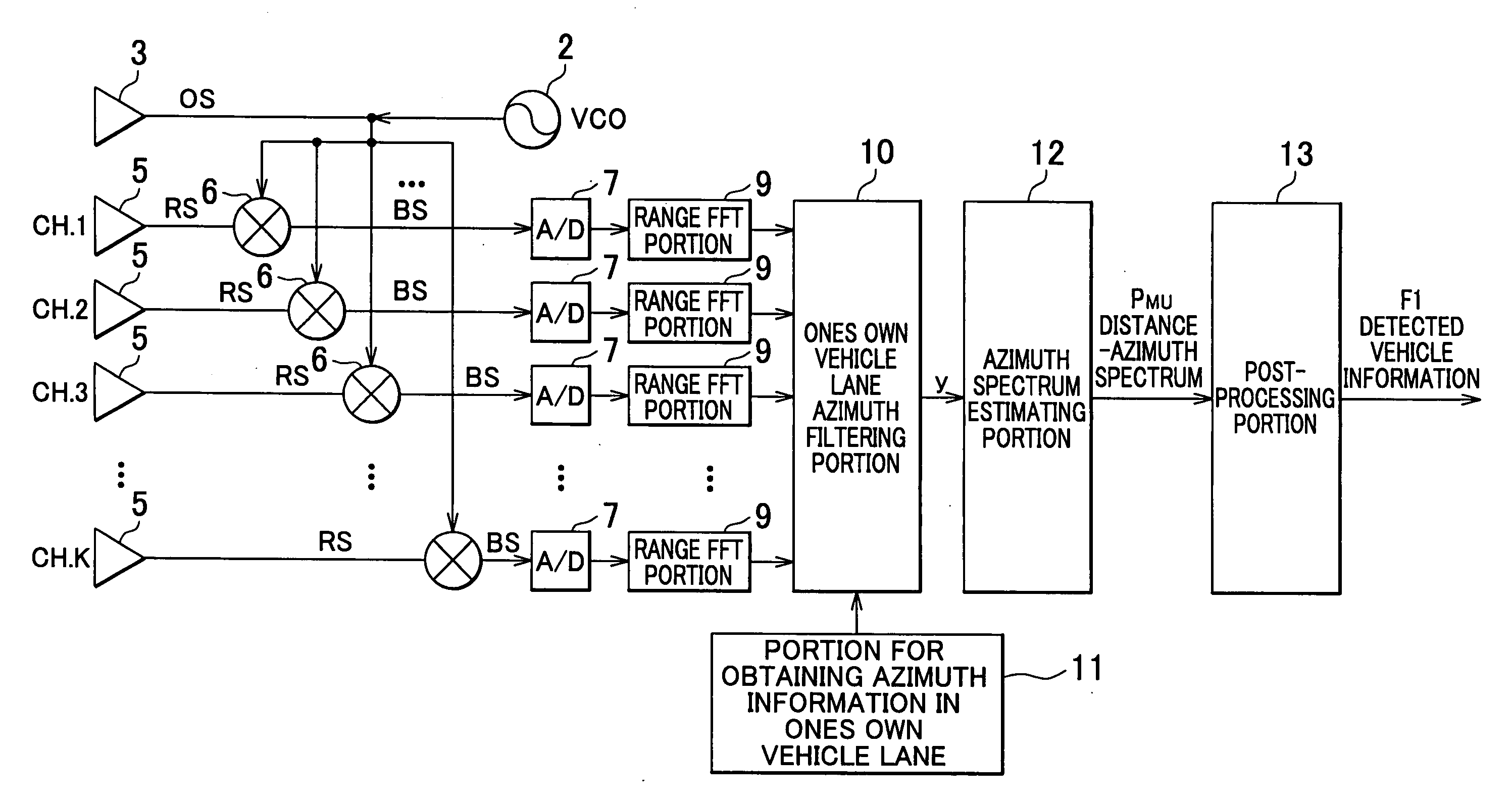
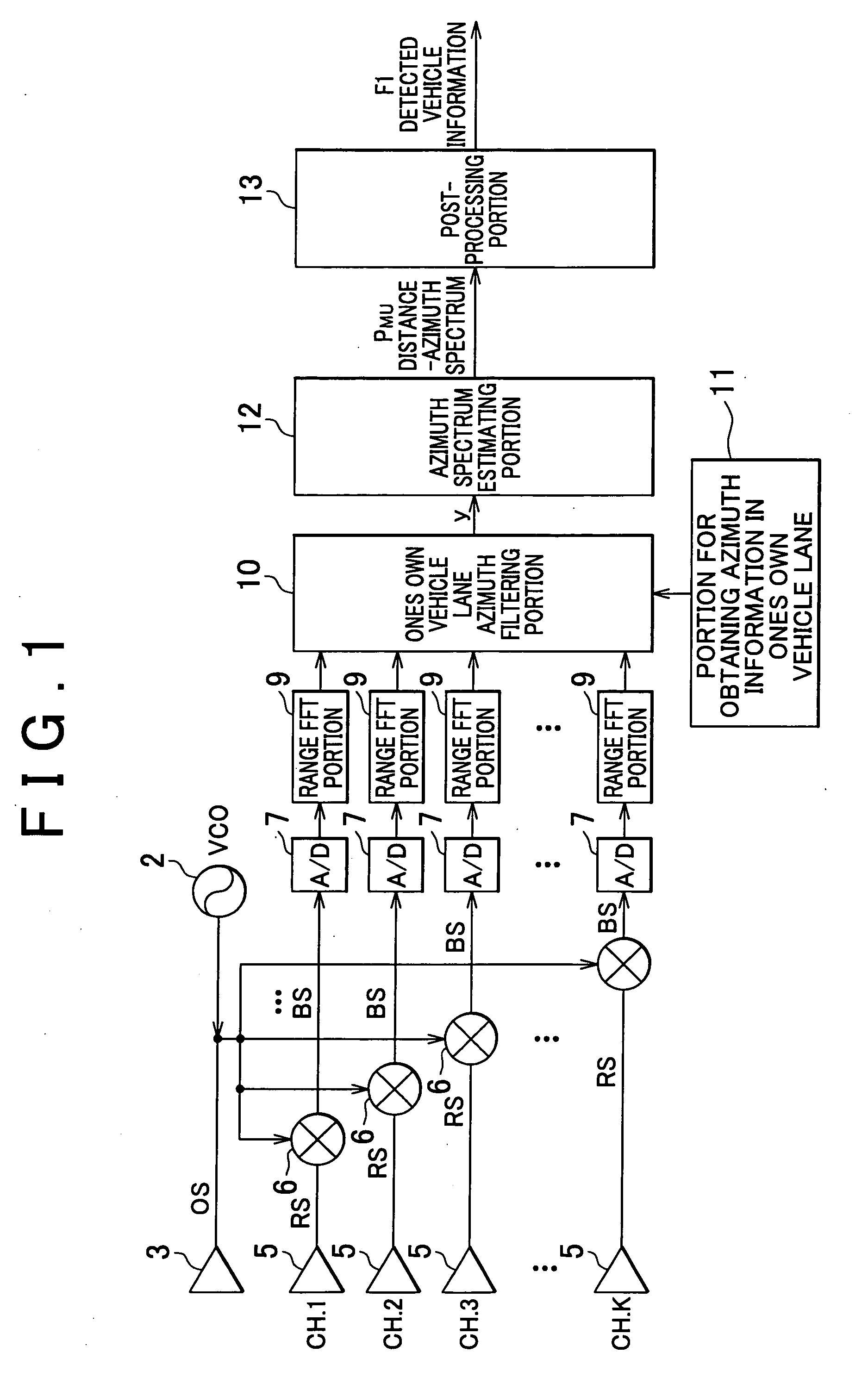
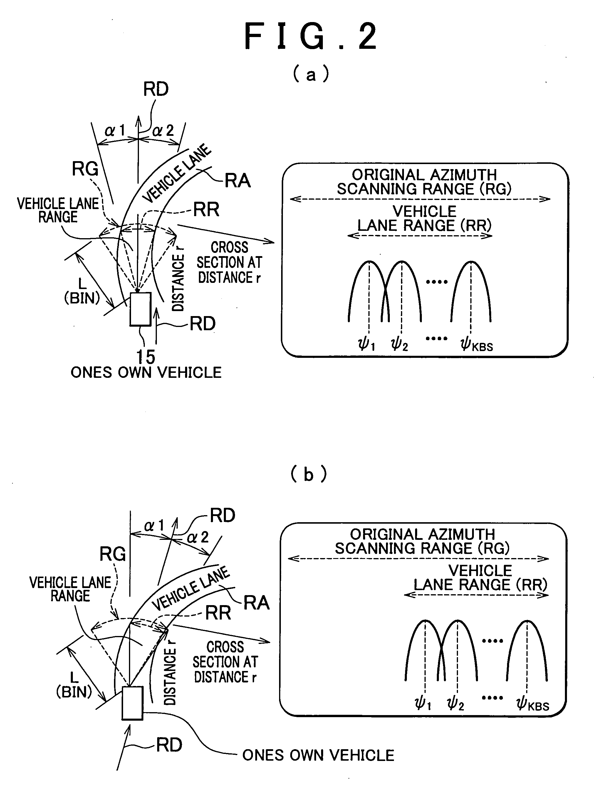
[0030]FIG. 1 is a block diagram showing an instance of a vehicle-mounted radar apparatus, and FIG. 2 is a view exemplarily showing a control for forming beams in a scanning range and a vehicle lane range of the vehicle-mounted radar apparatus.

[0031] As shown in FIG. 1, a vehicle-mounted radar apparatus 1 has a voltage controlled oscillator (VCO) 2, and a transmitting antenna 3 is connected with the oscillator 2. And, the vehicle-mounted radar apparatus has K numbers of receiving antennas 5 which are comprised of K channels, and the K numbers of these receiving antennas 5 comprise an array antenna. A mixer 6 connected with the oscillator 2 is connected with each receiving antenna 5. A range FFT (Fast Fourier Transform) portion 9 is connected with the mixer 6 through an A / D converter 7.

[0032] A ones own vehicle lane azimuth filtering portion 10 is connected with each range FFT portion 9, and...


PUM


Abstract

Apparatus has a transmitting antenna for radiating transmitting signals over a scanning range in the shape of a fan for a forward direction of ones own vehicle at a constant transmitting cycle, receiving antennas for receiving reflected waves by a target and for outputting receiving signals, spectrum computing means for computing a frequency complex amplitude spectrum from the receiving and transmitting signals, advancing direction computing means for computing an advancing direction of ones own vehicle, advancing direction element extracting means for extracting directional elements corresponding to the advancing direction from the frequency complex amplitude spectrum on the basis of the obtained advancing direction, and for outputting computed result data, distance-azimuth spectrum computing means for computing a distance-azimuth spectrum of ones own vehicle, and target detecting means for detecting the target which exists in a forward direction of ones own vehicle on the basis of the computed distance-azimuth spectrum.

Description

BACKGROUND OF THE INVENTION [0001] This invention relates to an electron scanning type of a vehicle-mounted radar apparatus which is used for detecting a preceding target which exists in a forward direction. [0002] A conventional vehicle-mounted radar apparatus for control on an inter-vehicle distance generally obtains a distance to a target and an azimuth as shown in a patent-related document 1 (will be mentioned later) in such a way that with an electron scanning type of radar, electromagnetic waves, such as millimetric waves, are radiated in order to obtain a distance to a target, such as a preceding vehicle which exists in a forward direction, and an azimuth, and two or more antennas receive reflected waves of the electromagnetic waves which have been reflected by a target, and an arithmetic processing is implemented on received signals with a well-known method, such as a distance spectrum conversion and an azimuth spectrum conversion. [0003] Generally, radar art has the followi...

Claims


Application Information

Patent Timeline
Patent Type & Authority Applications(United States)
IPC IPC(8): G01S13/42G01S13/93G01S13/931
CPCG01S13/589G01S13/60G01S2013/9375G01S2013/9353G01S13/931G01S2013/93271G01S2013/932
Inventor YAMANO, CHIHARUMIYAKE, YASUYUKI
Owner DENSO IT LAB
Why Eureka
Try Eureka