Antenna device, mobile terminal and RFID tag

Inactive Publication Date: 2007-01-11
TOSHIBA CLIENT SOLUTIONS CO LTD
View PDF15 Cites 21 Cited by
  • Summary
  • Abstract
  • Description
  • Claims
  • Application Information

AI Technical Summary

Problems solved by technology

Conventionally, there is a problem that radiation characteristics of an antenna are degraded in the case where a lossy dielectric such as a human body is present in the vicinity of the antenna.
However, in this constitution, the antenna itself becomes comparatively large, resulting in a problem that it is difficult to mount the antenna to a small terminal apparatus and the like.
Further, power is generally fed to a radio apparatus in an unbalanced state (for example by a coaxial feeder, a microstrip line and the like), but the dipole antenna is a balanced type element, and hence, a balance-unbalance converter (balun) is needed at a feed point.
This causes the radio apparatus to be complicated and makes the miniaturization of the apparatus difficult.

Method used


Image

  • Antenna device, mobile terminal and RFID tag
  • Antenna device, mobile terminal and RFID tag
  • Antenna device, mobile terminal and RFID tag

Examples


Embodiment Construction

[0025] In the following, embodiments according to the present invention will be described with reference to the accompanying drawings.

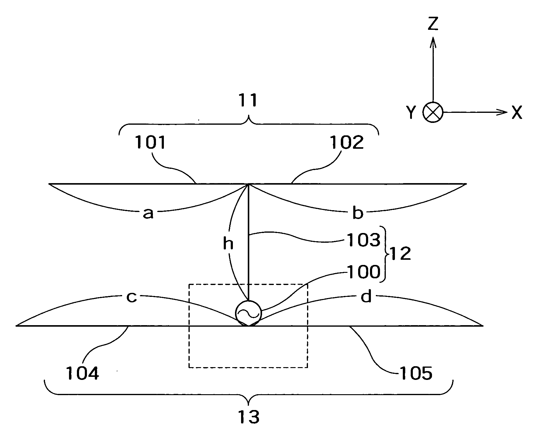
[0026]FIG. 1 shows an embodiment of an antenna device according to the present invention.

[0027] The antenna device has wire elements 101 to 105 made of a conductive material and a feed point 100. The wire elements 101 to 105 and the feed point 100 are positioned on a same plane. The wire elements are made of, for example copper.

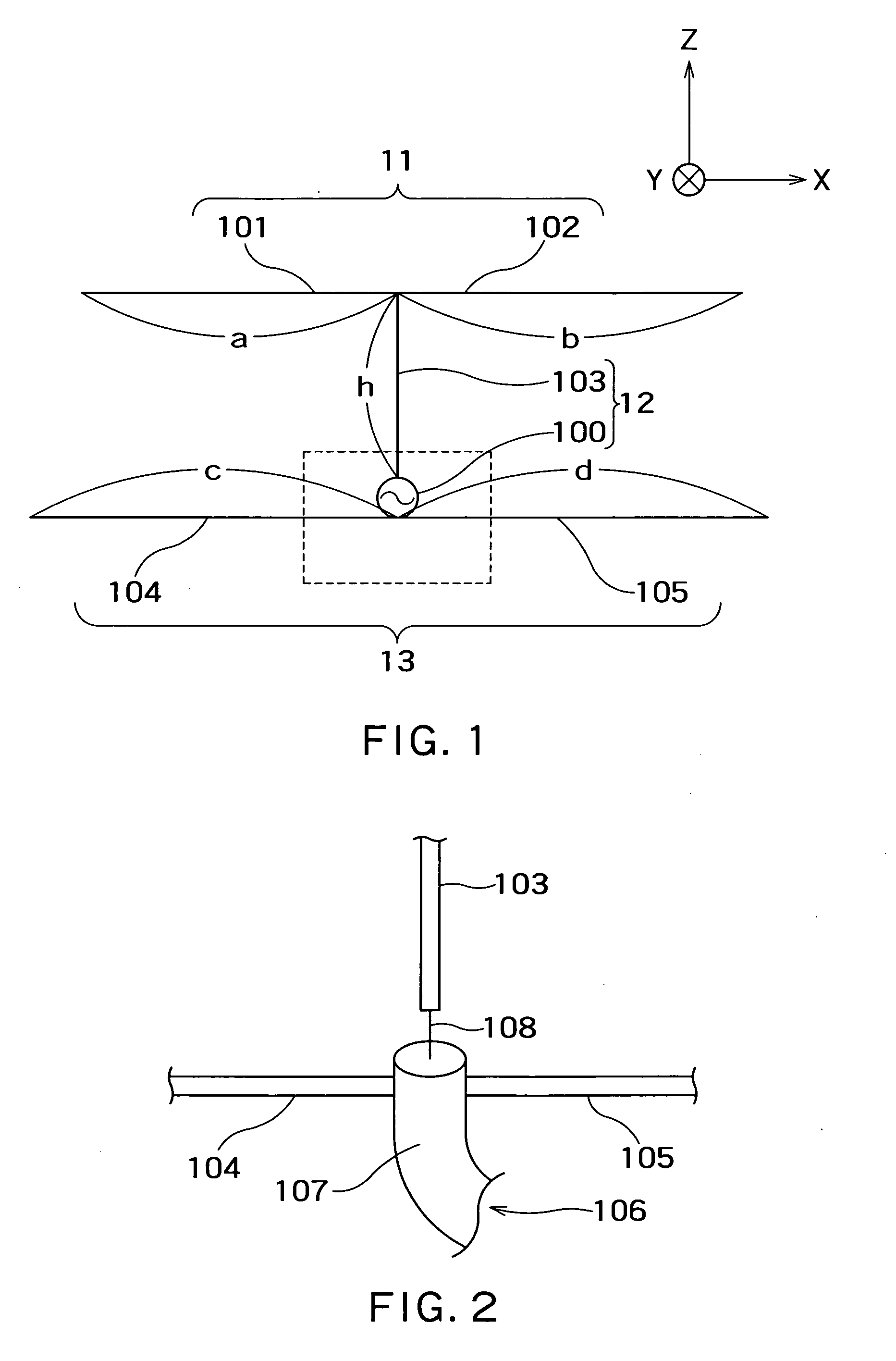
[0028] The wire elements 101, 102 are connected in straight line form. A first wire antenna element 11 includes the wire elements 101, 102. One end of the wire element 103 perpendicular to the wire elements 101, 102 is connected to the connecting point of the wire elements 101, 102, and the other end of the wire element 103 is connected to the feed point 100. A second wire antenna element 12 includes the wire element 103, or includes the wire element 103 and the feed point 100. The wire elements 104, 105 are connected in str...


PUM


Abstract

There is provided with an antenna device including: a first wire antenna element having a length about half a wavelength of a radio wave in use; a second wire antenna element which is in a same plane as the first wire antenna element and substantially perpendicular to the first wire antenna element, and which is connected to the first wire antenna element at one end; a third wire antenna element which is in the same plane as the first wire antenna element and substantially in parallel with the first wire antenna element, and which is connected to the second wire antenna element; and a feed point provided on the second wire antenna element.

Description

CROSS-REFERENCE TO RELATED APPLICATIONS [0001] This application is based upon and claims the benefit of priority from the prior Japanese Patent Applications No. 2005-201915 filed on Jul. 11, 2005, the entire contents of which are incorporated herein by reference. BACKGROUND OF THE INVENTION [0002] 1. Field of the Invention [0003] The present invention relates to an antenna device available for small communication devices, such as for example a wearable apparatus, a mobile telephone and PHS, which are used in the vicinity of a human body, to a mobile terminal equipped with the antenna device, and to an RFID tag. [0004] 2. Related Art [0005] Conventionally, there is a problem that radiation characteristics of an antenna are degraded in the case where a lossy dielectric such as a human body is present in the vicinity of the antenna. In order to solve this problem, it is considered to reduce absorption of a radio wave by the human body using an antenna having unidirectional directivity ...

Claims


Application Information

Patent Timeline
IPC IPC(8): H01Q1/24H01Q5/10
CPCH01Q1/2225H01Q19/28H01Q19/24H01Q9/20
Inventor YAMADA, AKIKOHIGAKI, MAKOTOSEKINE, SHUICHI
Owner TOSHIBA CLIENT SOLUTIONS CO LTD
Why Eureka
Try Eureka