Satellite position measurement system

Inactive Publication Date: 2005-03-08
KK TOPCON
View PDF18 Cites 155 Cited by
  • Summary
  • Abstract
  • Description
  • Claims
  • Application Information

AI Technical Summary

Benefits of technology

The object of the present invention is to provide a GPS positioning system (Satellite positioning system) that can deal flexibly with

Problems solved by technology

Furthermore, when an obstacle or the like exists around the antenna, a satellite may exists from which radio wave cannot be received depending on the time.
Conventionally, before setting out for a measurement operation, arrangement information of the GPS satellites has been processed on a personal computer or the like after the obstacle viewed from an observation point was predicted, and thus the time unsuitable for the measurement operation had to be set.
However, unlike static positioning performed by fixing the antenna, in kinematic positioning having the premise that the positioning operation is performed while moving the antenna, there have been many cases where positioning operation was difficult at a point where positioning was originally planed or where an operator could not dea

Method used


Image

  • Satellite position measurement system
  • Satellite position measurement system
  • Satellite position measurement system

Examples


Embodiment Construction

The preferred embodiments of the invention will be described as follows based on the drawings.

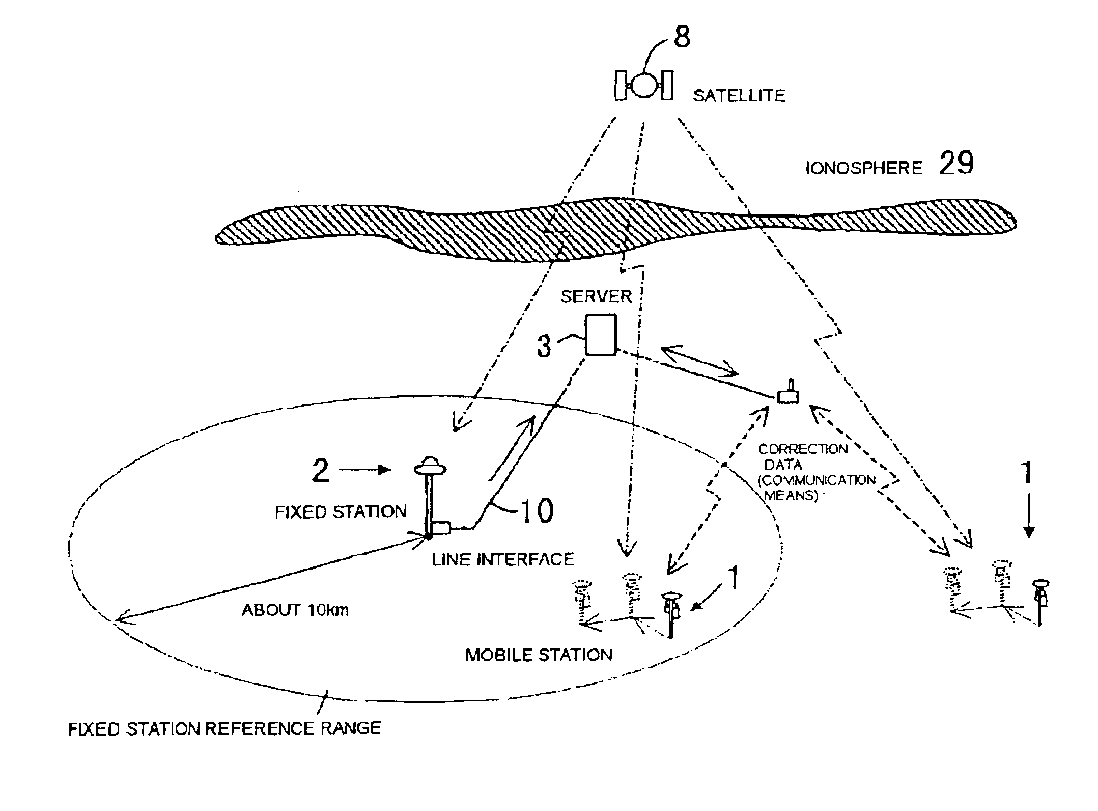
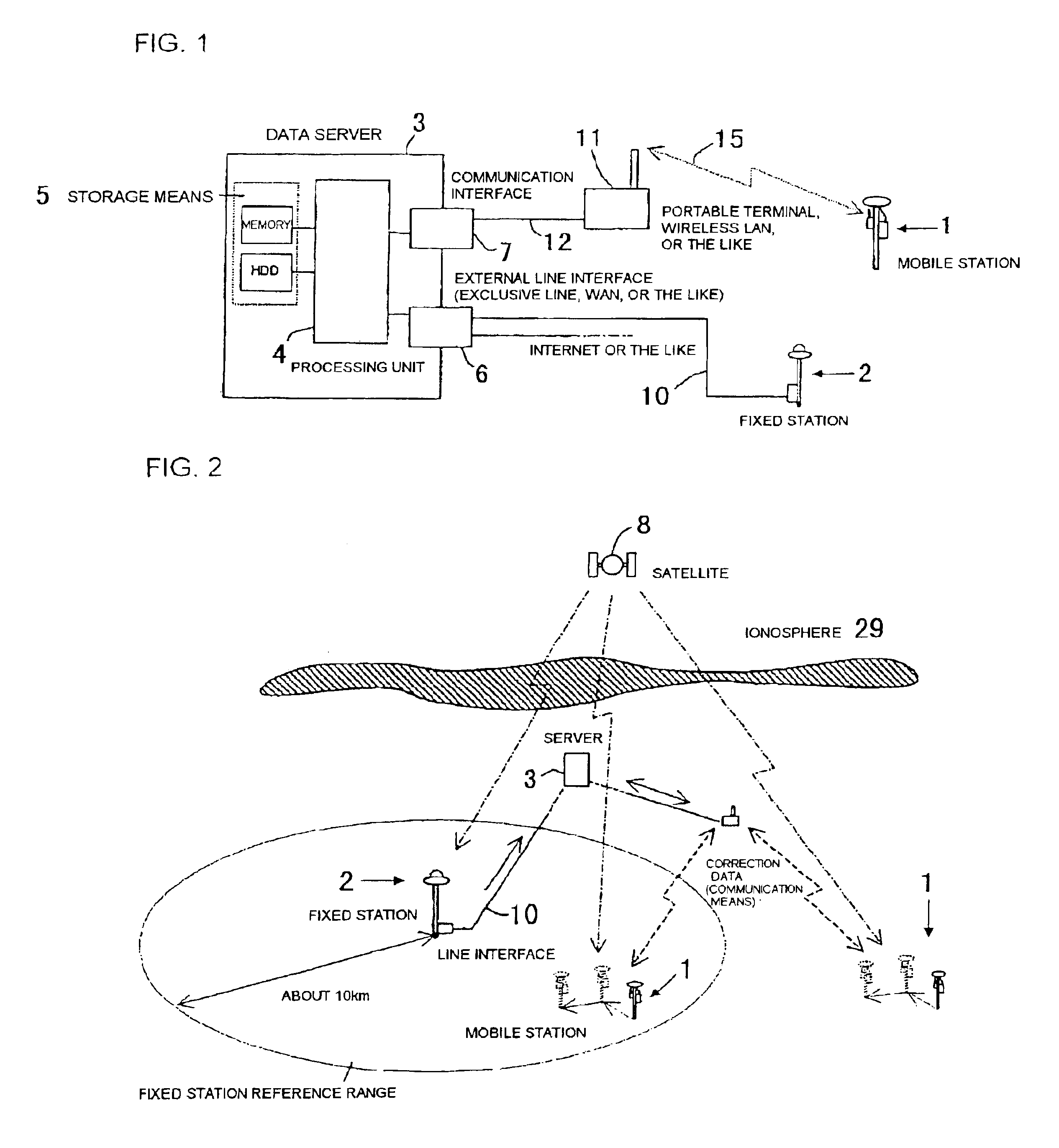
FIG. 1 is the entire configuration view showing an embodiment of the satellite positioning system according to the present invention.

The satellite positioning system according to the present invention consists of at least one mobile station 1, a plurality of the fixed stations 2, and an arithmetic processing unit (a data server 3, preferably) connected with the mobile station 1 and the fixed stations 2 via communication means.

The data server 3 consists of a central processing unit 4, a storage means 5, an interface units 6, 7 and the like.

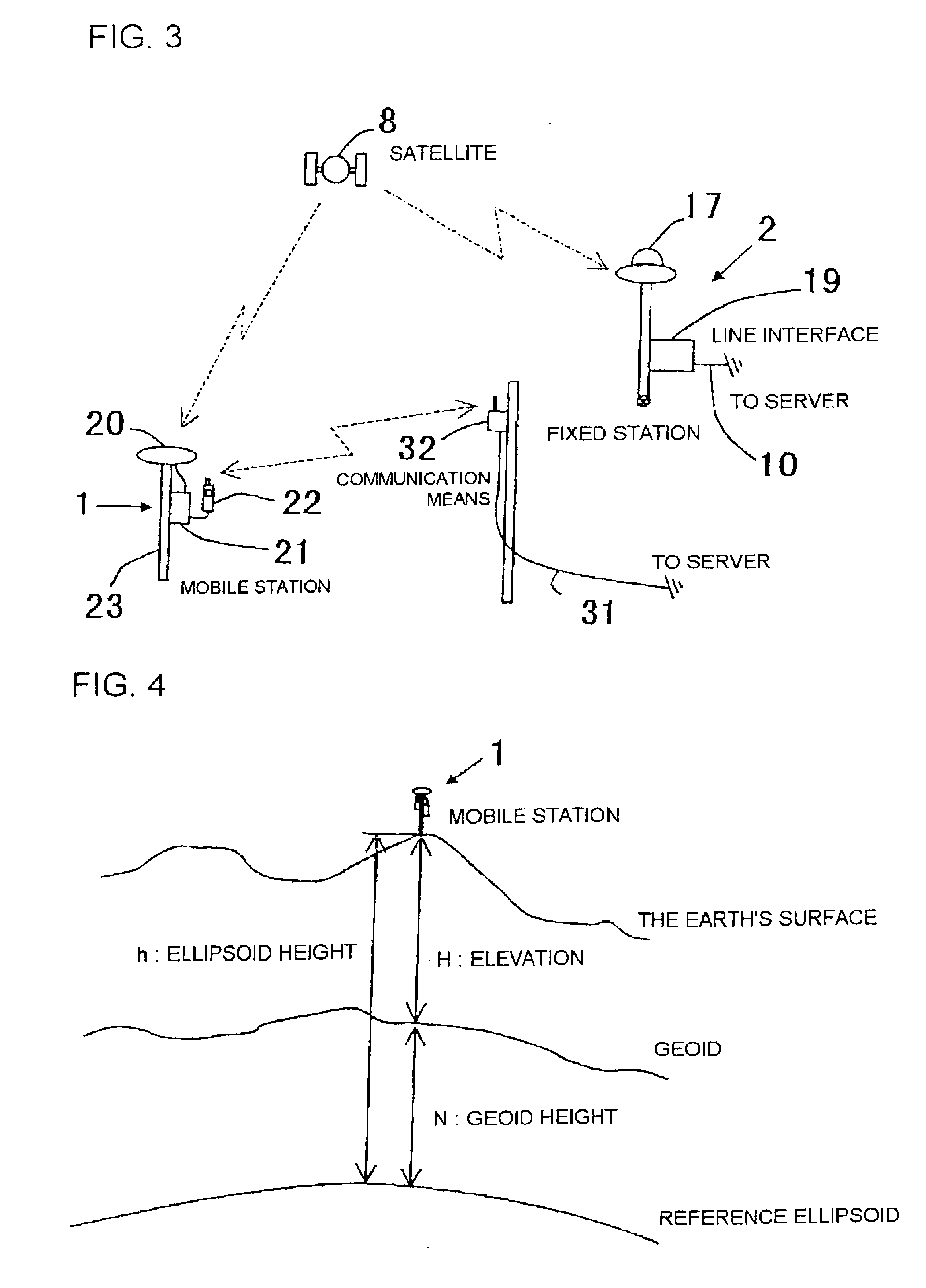
The mobile station 1 has: a receiving antenna 20; a receiver 21; communication means 22 capable of two-way communication with the data server 3 (or an interface connectable with the communication means); and display means (not shown) capable of displaying various kinds of information for the operator.

The receiver 21 of the mobile station 1 has storage mean...


PUM


Abstract

A GPS positioning system that has: at least one mobile station to measure a positional coordinate by receiving radio wave from a satellite; a plurality of fixed stations that have predetermined positional coordinates and receive radio wave from the satellite; and arithmetic processing means, which is connected with at least one mobile station and a plurality of fixed stations via communication, and that transmits correction data suitable for the mobile station to the mobile station based on positioning data transmitted from the mobile station.

Description

BACKGROUND OF THE INVENTION1. Technical Field of the InventionThe present invention relates to a GPS positioning system (Satellite positioning system) in which a positional coordinate can be found by receiving radio wave from a satellite, and a data server for GPS positioning.2. Prior ArtKinematic positioning in a GPS is a survey method where a pair of antenna and a receiver are arranged in a fixed manner at a reference point whose positional coordinate is known and another pair of movable antenna and receiver perform measurement in a short time while sequentially moving among a large number of survey points.There exists a real-time kinematic positioning (hereinafter, referred to as an RTK) as a developed type of the kinematic positioning. The RTK is a positioning method where a position being a measurement result can be obtained in a real-time.As shown in FIG. 6, a fixed station 2 that consists of antenna and receiver is arranged at the reference point whose coordinate is known and...

Claims


Application Information

Patent Timeline
IPC IPC(8): G01S5/14G01S1/00G01C15/00G01S19/01G01S19/04G01S19/07G01S19/43
CPCG01S19/43G01S19/07G01S19/072G01S19/073
Inventor MIYASAKA, KOJIMORI, MASAKAZUSAKAKI, KAZUYUKITAKASU, KENICHIKOBAYASHI, YUJI
Owner KK TOPCON
Why Eureka
Try Eureka