Geographic data collecting system

a geographic data and data collection technology, applied in the field of portable type geographic data collection system, can solve the problems of difficult to specify a measuring point on an object to be measured, complicated procedure such as matching the acquired images with measurement data, and inconvenient, etc., to achieve the effect of simple and convenient manner

Active Publication Date: 2007-01-11
KK TOPCON
View PDF13 Cites 147 Cited by
  • Summary
  • Abstract
  • Description
  • Claims
  • Application Information

AI Technical Summary

Benefits of technology

[0010] It is an object of the present invention to provide a geographic data collecting system, by which it is possible to acquire an image of an object to be measured, to measure a distance to the object to be measured and also to specify measuring points in the image, and further, to facilitate the collecting of geographic data with image and to simplify the procedure to acquire image data and to perform measurement on the object to be measured.
[0014] According to the present invention, it is possible to provide a geographic data collecting system, comprising a distance measuring unit for projecting a distance measuring light and for measuring a distance to an object to be measured, a camera for taking an image in measuring direction, a display unit for displaying the pickup image, a touch panel provided to correspond to a screen position of the display unit, a tilt sensor for detecting a tilting of the measuring direction, and an arithmetic unit for calculating a distance to the object to be measured by giving consideration on the tilting in the measuring direction and a point-to-point distance as specified on the image by specifying two or more points of the object to be measured on a displayed image via the touch panel. As a result, operation can be confirmed and performed on the image, and measuring operation can be performed without performing complicated procedure, and image data with a distance measurement data can be collected in simple and easy manner.

Problems solved by technology

This is not suitable for the case where many geographic data must be acquired within short time.
Because this portable type distance measuring system is not provided with an image pickup device, and it is difficult to specify a measuring point on an object to be measured.
As a result, complicated procedure such as matching the acquired images with measurement data are needed.

Method used


Image

  • Geographic data collecting system
  • Geographic data collecting system
  • Geographic data collecting system

Examples


embodiment 1

[0044] Description will be given on the measurement relating to an object to be measured 23 by referring to FIG. 3 and FIG. 4. The measurement given below indicates a case where a telephone pole is selected as the object to be measured 23.

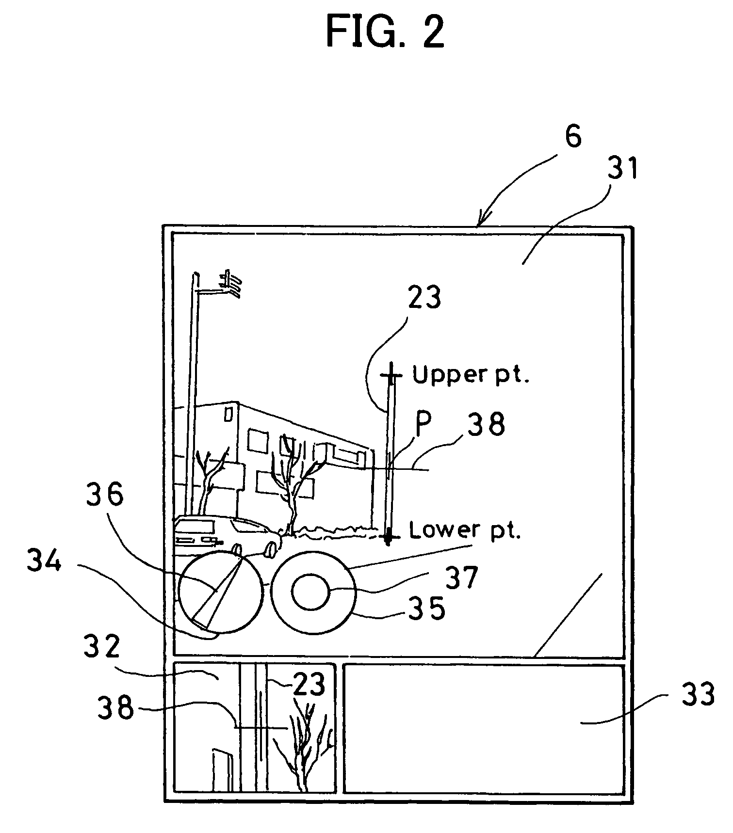
[0045] (Step 01) From an image pickup point O1, the geographic data collecting system 1 is directed toward the object to be measured 23, and the geographic data collecting system 1 is maintained at horizontal position. The geographic data collecting system 1 is directed toward the object to be measured 23. On the main screen 31, the cursor 38 is aligned with a measuring point P on the object to be measured 23 in an image displayed on the screen. The alignment condition of the cursor 38 to the object to be measured 23, is confirmed by an enlarged view on the first sub-screen 32.

[0046] (Step 02) When the measuring point P is determined, a distance measuring button (not shown) is operated by the operation unit 7, and distance measurement is carried ...

embodiment 2

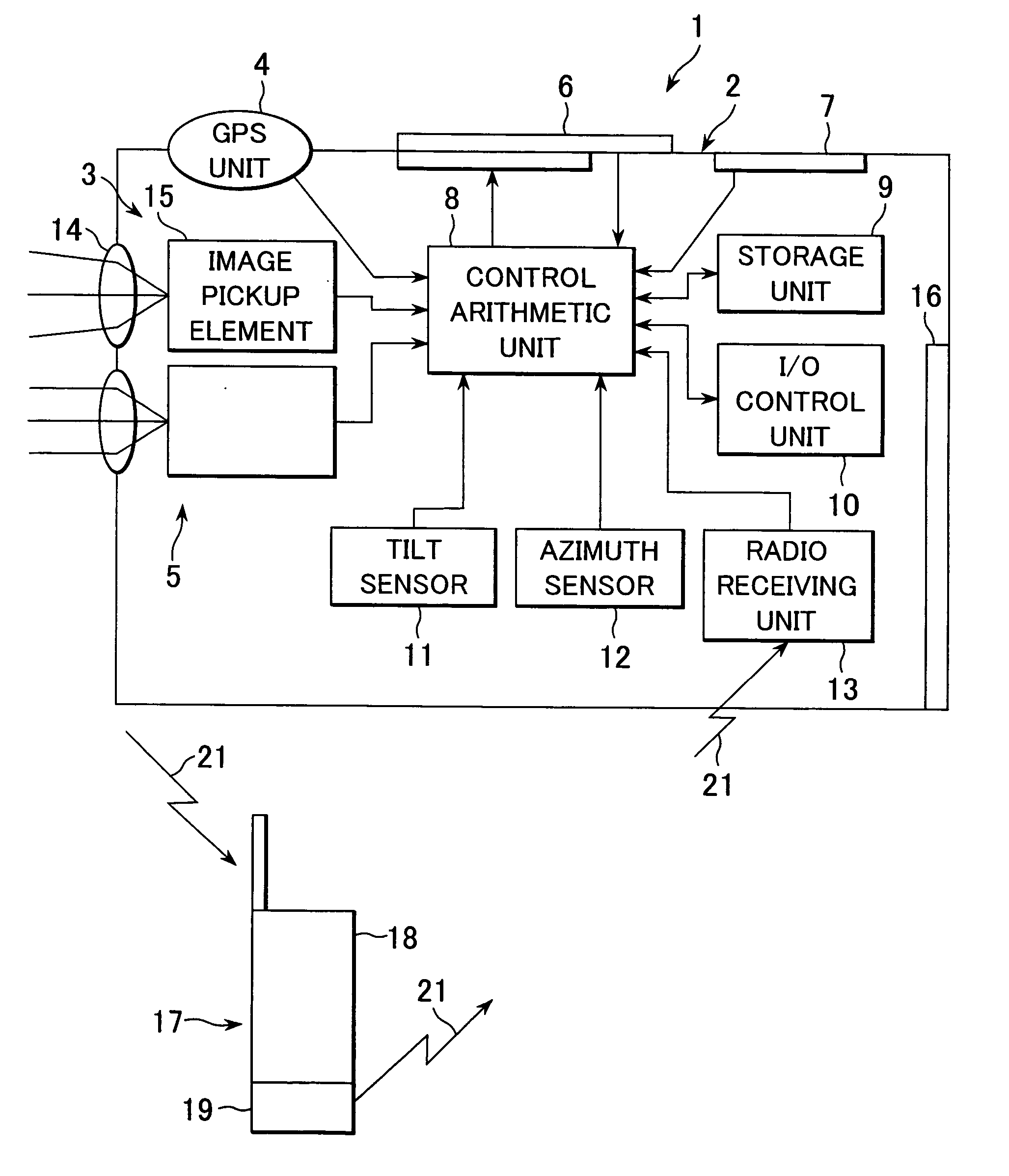
[0056] Next, description will be given on a case where a single measuring point P on the object to be measured 23 is measured from two measuring points referring to FIG. 1 and FIG. 5 to FIG. 7.

[0057] (Step 01) From a first image pickup point O1, the object to be measured 23 is collimated by an image on the display unit 6. By setting a certain position of the object to be measured 23 as a measuring point P, the measuring point P is aligned with the cursor 38 (collimating position).

[0058] (Step 02) By operating a button on the operation unit 7, an image is taken from the first image pickup point O1 to the object to be measured 23, and an image 25A of the object to be measured 23 is acquired. The measuring point P is stored in the storage unit 9 as a measuring point PA of the image 25A. It is preferable that the measuring point P has specific features easy to identify, e.g. it is preferable that a point such as a window corner, an edge of a building, etc. is selected as the measuring...

embodiment 3

[0068] Next, description will be given on a case where two or more measuring points P are measured on the object to be measured 23 from two measuring points and a length of straight line and an area of the object to be measured 23 are calculated by referring to FIG. 1 and FIG. 8 to FIG. 10.

[0069] (Step 01) The object to be measured 23 is collimated from the first image pickup point O1 in an image on the display unit 6. Required position on the object to be measured 23 is set as a measuring point P1, and the measuring point P1 is aligned with the cursor 38 (collimating position).

[0070] (Step 02) By operating a button on the operation unit 7, an image is taken from the first image pickup point O1 toward the object to be measured 23, and an image 25A is acquired on the object to be measured 23. The measuring point P1 is stored in the storage unit 9 as a measuring point PA1 of the image 25A. It is preferable that the measuring point P1 has specific features easy to identify. It is pre...


PUM


Abstract

A geographic data collecting system, comprising a distance measuring unit for projecting a distance measuring light and for measuring a distance to an object to be measured, a camera for taking an image in measuring direction, a display unit for displaying the pickup image, a touch panel provided to correspond to a screen position of the display unit, a tilt sensor for detecting a tilting of the measuring direction, and an arithmetic unit for calculating a distance to the object to be measured by giving consideration on the tilting in the measuring direction and a point-to-point distance as specified on the image by specifying two or more points of the object to be measured on a displayed image via the touch panel.

Description

BACKGROUND OF THE INVENTION [0001] The present invention relates to a portable type geographic data collecting system, and in particular, relates to a geographic data collecting system, by which it is possible to acquire an image data of a measuring point, to specify the measuring point in the image, to perform measurement, etc. while visually confirming the measuring point, and to collect the measurement result together with the image data. [0002] In recent years, a navigation system using an electronic map has been propagated. The navigation system is provided on vehicles or provided on handy phones(cellular phones) as additional function and is used. [0003] With the propagation of the navigation system, geographic data required for electronic map has also been increasingly diversified, and there are strong demands on more precise and minute geographic data and on symbol marks, 3-dimensional images, etc. which should be added to the map to facilitate visual checking. [0004] For in...

Claims


Application Information

Patent Timeline
Patent Type & Authority Applications(United States)
IPC IPC(8): G01C3/08G06K9/00G01C1/00
CPCG01C3/00G01C11/00G01C21/005G01C15/00G01C11/14
Inventor OTANI, HITOSHITANAHASHI, ATSUSHIINABA, HIROSHIISHIDA, TAKESHIKANEKO, JUNKI
Owner KK TOPCON
Why Eureka
Try Eureka