Lamp housing with interior cooling by a thermoelectric device

Inactive Publication Date: 2007-01-11
VARROC LIGHTING SYST
View PDF24 Cites 35 Cited by
  • Summary
  • Abstract
  • Description
  • Claims
  • Application Information

AI Technical Summary

Benefits of technology

[0009] In overcoming the drawbacks and the limitations of the known technologies, a lamp system with enhanced heat dissipation capabilities is disclosed. The system includes a housing, wall portions defining a cavity,

Problems solved by technology

Even with the above advantages, LEDs have rarely been utilized to provide forward lighting for an automobile.
This is because LEDs have the drawback of losing light output at higher diode junction temperatures compared to a more commonly utilized incandescent bulb.
If the

Method used


Image

  • Lamp housing with interior cooling by a thermoelectric device
  • Lamp housing with interior cooling by a thermoelectric device

Examples


Embodiment Construction

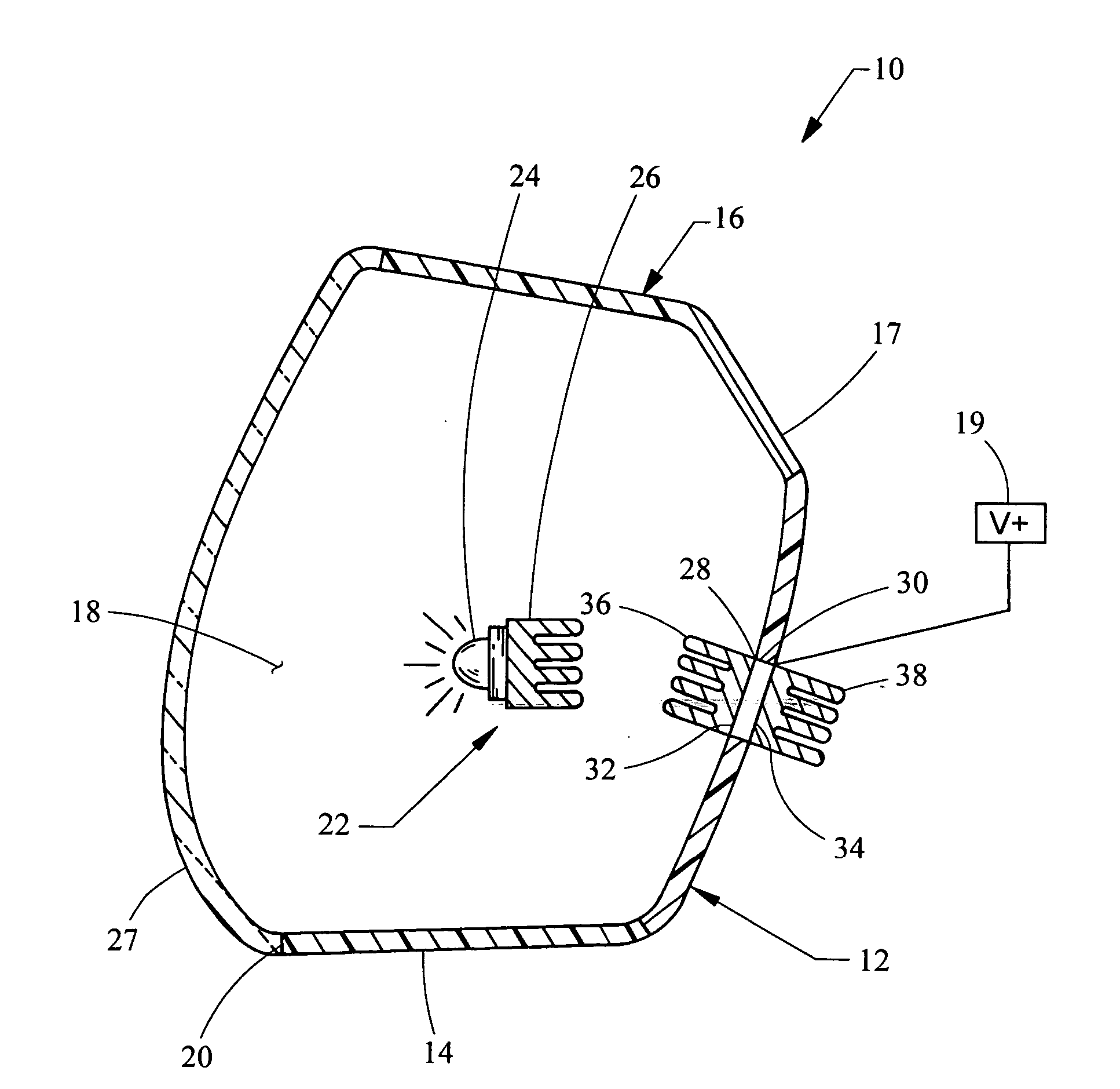
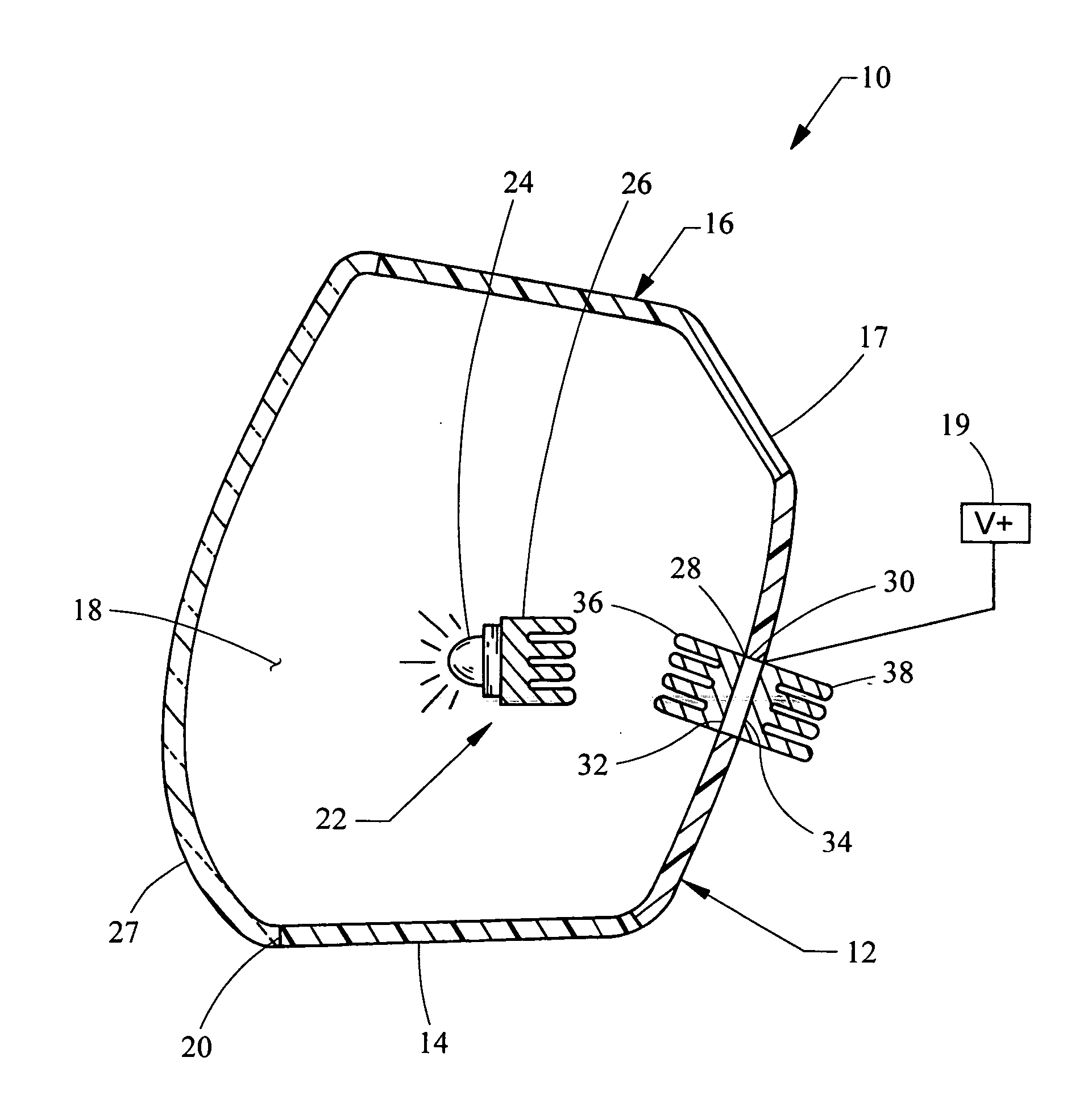
[0014] Referring now to the FIGURE, a lamp system 10 is shown. Preferably, the lamp system 10 is used to provide for forward lighting of an automobile. However, the lamp system 10 may be used to provide lighting for fog lamps, brake lamps or any other lamps that are part of, but not limited to, an automobile.

[0015] The lamp system 10 includes a housing 12 having first and second side wall portions 14, 16 and a back wall portion 17 defining a cavity 18 and an opening 20. Generally, the wall portions 16, 14, are constructed of a rigid and / or insulating material, such as plastic. However, the wall portions 14, 16 of the housing 12 may be made of any material suitable for this purpose.

[0016] A transparent lens cover 27 is coupled to the housing 12 such that the opening 20 of the cavity 18 is closed. The transparent lens cover 27 is preferably made of a transparent plastic but may be made of any transparent material, such as glass.

[0017] Rigidly mounted within the cavity 18 by a brack...


PUM


Abstract

A lamp system having a housing, wall portions defining a cavity and an opening. A light source, generally an LED, is located within the cavity and at least one thermoelectric device is disposed in one of the wall portions. The thermoelectric device has a first side oriented towards the cavity and the second side oriented away from the cavity. When in operation, the thermoelectric device will transfer heat from inside the cavity, via the first side of the thermoelectric device, to the second side of the thermoelectric device.

Description

BACKGROUND [0001] 1. Field of the Invention [0002] The present invention generally relates to automobile lighting systems and more particularly to automobile lighting systems utilizing light emitting diodes (“LEDs”). [0003] 2. Description of the Known Technology [0004] Currently, LEDs are typically used in automobiles to provide lighting for the interior cluster and the brake lights of an automobile. Used in such applications, LEDs have several advantages over traditional incandescent light bulbs. For example, LEDs have increased brightness, faster response times, low electrical current requirements, longer operating life and can be surface mounted, unlike traditional incandescent bulbs which typically require through-hole mounts. [0005] Even with the above advantages, LEDs have rarely been utilized to provide forward lighting for an automobile. This is because LEDs have the drawback of losing light output at higher diode junction temperatures compared to a more commonly utilized in...

Claims


Application Information

Patent Timeline
IPC IPC(8): F21V29/00
CPCF21S48/1154F21S48/215F21S48/325F21S48/326F21Y2101/02F21V29/004F21V29/02F21V29/30F21S48/328F21V29/56F21V29/60F21V29/70F21Y2115/10F21S41/143F21S43/14F21S45/42F21S45/43F21S45/46F21S45/47
Inventor CHINNIAH, JEYACHANDRABOSESAYERS, MITCHELL E.SINGH, HARVINDERTARNE, JAMES D.DUSZKIEWICZ, ALAN J.LYON, PAUL A.
Owner VARROC LIGHTING SYST
Why Eureka
Try Eureka