Piezoelectric actuator and electronic equipment with piezoelectric actuator

Active Publication Date: 2007-01-11
SEIKO EPSON CORP
View PDF2 Cites 17 Cited by
  • Summary
  • Abstract
  • Description
  • Claims
  • Application Information

AI Technical Summary

Benefits of technology

[0060] According to the present invention, the vibrator is securely cushioned during impact without obstructing the vibration of the vibrator merely by designing spaces having specific dimens

Problems solved by technology

With timepieces, cameras, mobile toys, or other electronic devices provided with such piezoelectric actuators, the operation may be affected by the fact that the vibrator of the piezoelectric actuator and the rotor or other objects driven by the piezoelectric actuator may be brought out of alignment by external impact that occurs when the device is dropped, and damages may occur if the impact is severe.
Particularly, the component that supports and secures the vibrator is generally thin and f

Method used


Image

  • Piezoelectric actuator and electronic equipment with piezoelectric actuator
  • Piezoelectric actuator and electronic equipment with piezoelectric actuator
  • Piezoelectric actuator and electronic equipment with piezoelectric actuator

Examples


first embodiment

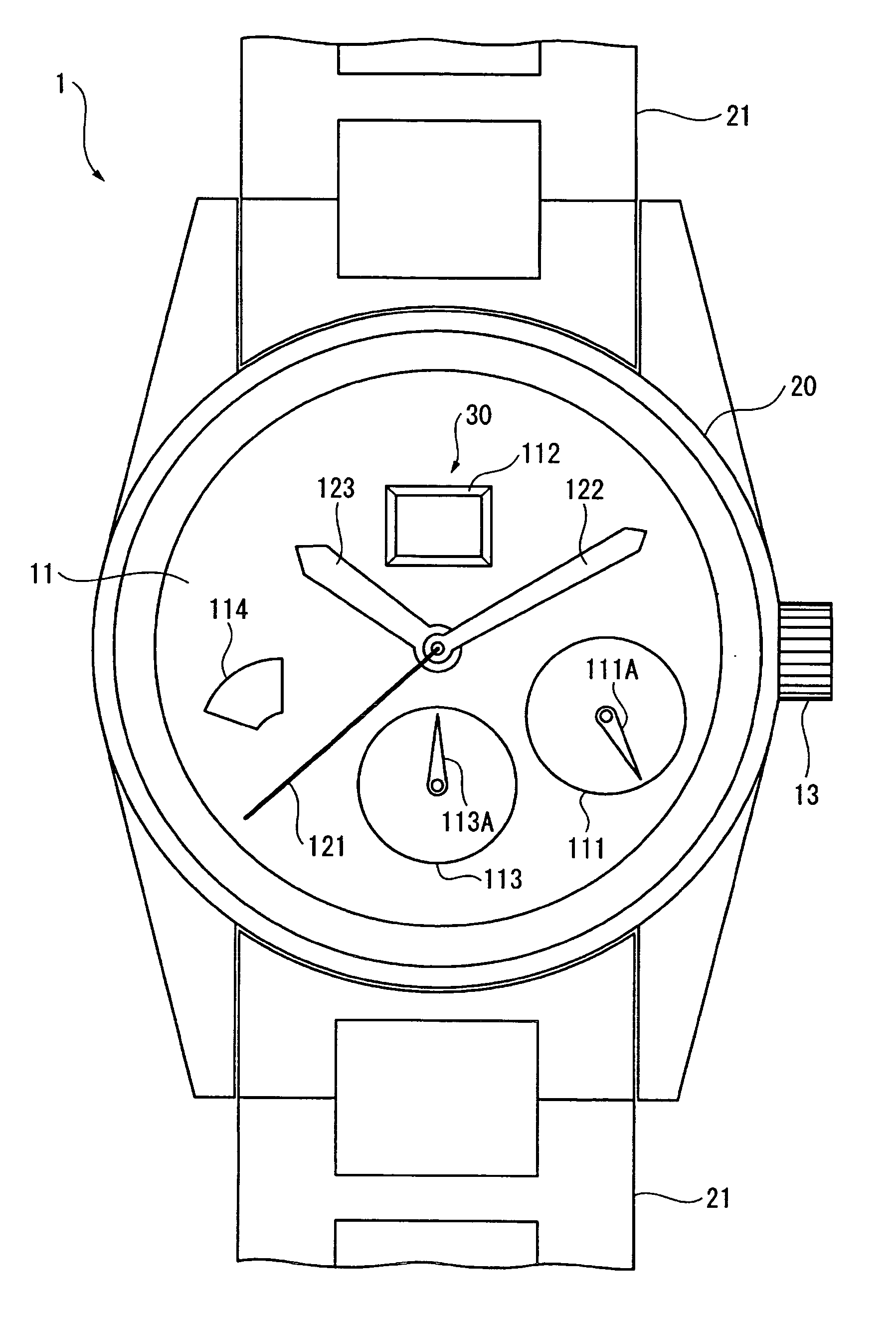
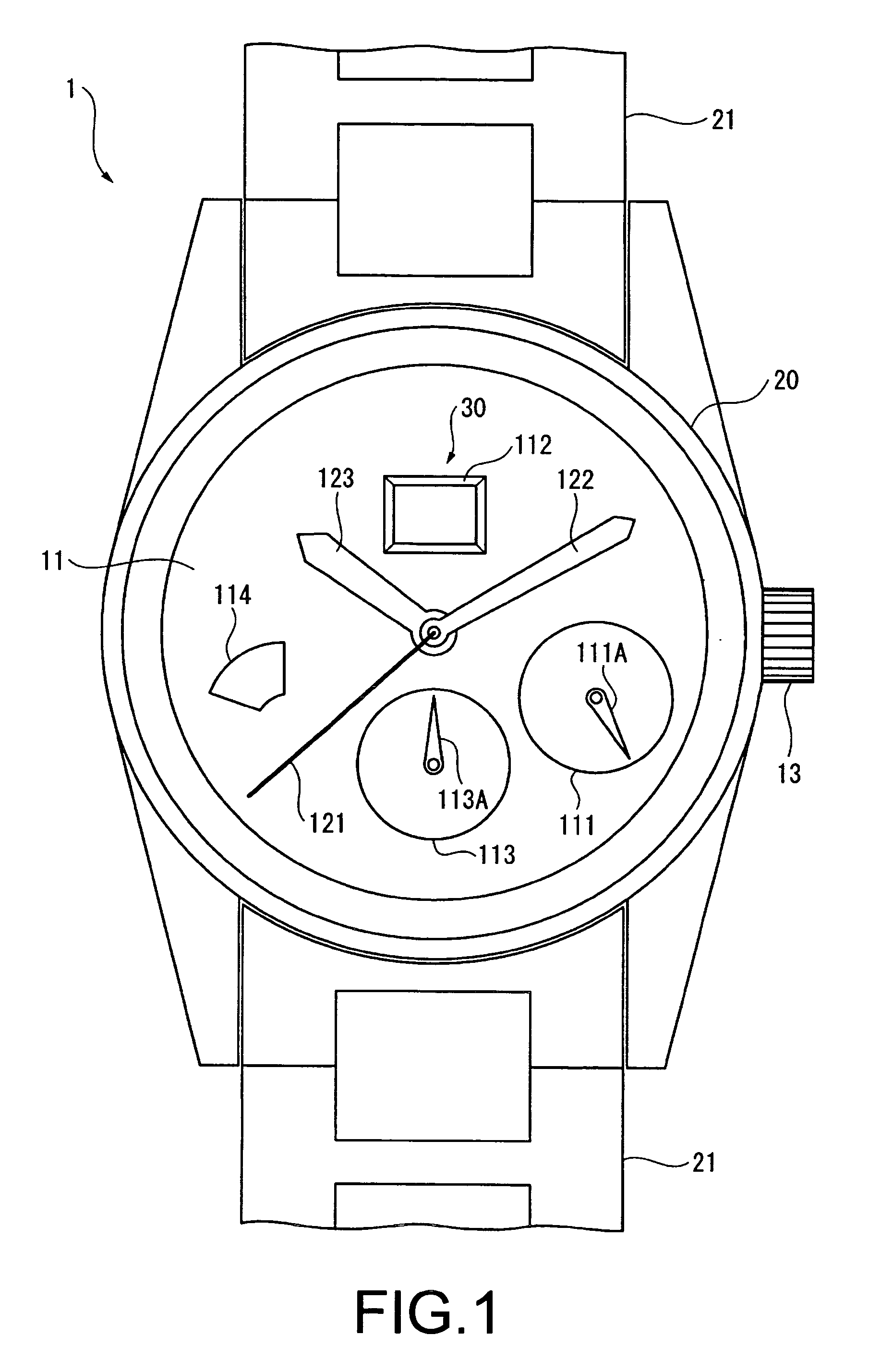
[0071]FIG. 1 is a diagram showing the external configuration of a wristwatch 1 according to the first embodiment of the present invention.

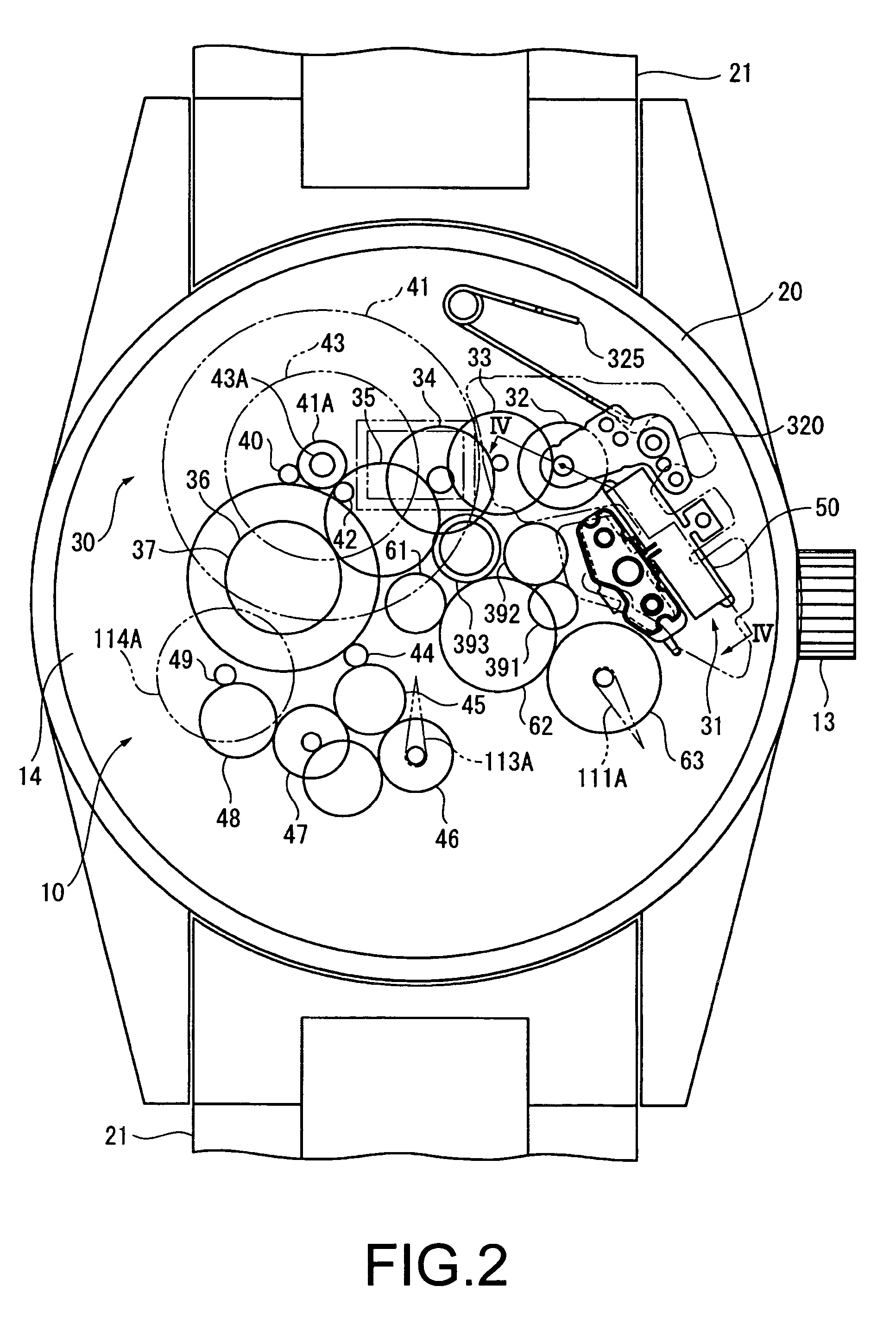
[0072] The wristwatch 1 (watch) comprises a movement 10 (FIG. 2) and a case 20 for housing the movement 10, and has a wristband 21 provided to the 12:00 position and the 6:00 position of the wristwatch 1. The timepiece may be a quartz timepiece, a mechanical timepiece, or an electronically controlled mechanical timepiece, but the wristwatch 1 of the present embodiment is configured as an analog quartz timepiece.

[0073] The wristwatch 1 has a disc-shaped dial 11, a seconds hand 121, a minute hand 122, an hour hand 123, and a crown 13.

[0074] Also, a circular 24-hour display unit 111 is provided to the dial 11, and the hours “0” through “23” are indicated by the rotation of a 24-hour display hand 111A in this 24-hour display unit 111.

[0075] Furthermore, the wristwatch 1 comprises a calendar mechanism 30 for displaying the date, and this calendar m...

second embodiment

[0171] Next, the second embodiment of the present invention will be described.

[0172] In the following descriptions, element that are similar to those of the above-described embodiment are denoted by the same numerical symbols, and descriptions thereof are omitted or simplified.

[0173] The present embodiment differs from the first embodiment in that spaces of specific dimensions are formed between the surface of the vibrator 50 and the main plate and pressing plate that are disposed on either side of the vibrator 50.

[0174]FIG. 8 is a cross-sectional side view of a piezoelectric actuator 71, a main plate 74 as a base member, and a pressing plate 75 in the present embodiment.

[0175] A pin part 741 is formed in the main plate 74 as an opposing part that extends in the thickness direction (substantially the same direction as the stacking direction of the reinforcing plate 51 and the piezoelectric elements 52, 53) of the wristwatch 1 towards a free end FR of the vibrator 50.

[0176] Also...


PUM


Abstract

To provide a piezoelectric actuator whereby impact resistance can be greatly improved without complicating the design or causing a reduction in drive efficiency.
When a piezoelectric actuator 31 is incorporated into a main plate 14, an arm part 513 of a vibrator 50 is disposed across from a protrusion 144 via spaces SP1, SP2 having specific dimensions. With the presence of these spaces SP1, SP2, a free end FR moves freely within the spaces SP1, SP2 during driving, but a vibrating part 511 is captured at the free end FR by the protrusion 144 when external impact is applied, and the vibrating part 511 can therefore be prevented from moving beyond the dimensions of the spaces. Resistance against impact from falling can thereby be easily and greatly improved without reducing the drive efficiency, and the usual difficulty of reconciling both drive efficiency and impact resistance can be resolved.

Description

FIELD OF THE INVENTION [0001] The present invention relates to piezoelectric actuator, and to an electronic device comprising the same. BACKGROUND OF THE INVENTION [0002] In conventional practice, piezoelectric actuators for driving driven objects by the vibration of a vibrator having a piezoelectric element have been used in the calendar mechanisms of timepieces, the zoom mechanisms or auto-focus mechanisms of cameras, the drive mechanisms of mobile toys, and the like. [0003] With timepieces, cameras, mobile toys, or other electronic devices provided with such piezoelectric actuators, the operation may be affected by the fact that the vibrator of the piezoelectric actuator and the rotor or other objects driven by the piezoelectric actuator may be brought out of alignment by external impact that occurs when the device is dropped, and damages may occur if the impact is severe. Particularly, the component that supports and secures the vibrator is generally thin and fragile so as not d...

Claims


Application Information

Patent Timeline
IPC IPC(8): G04C21/16G04C3/12H01L41/09H01L41/18H01L41/187H01L41/193H02N2/00
CPCG04C3/12H02N2/103H02N2/0055H02N2/004
Inventor KITAHARA, JOJISAWADA, AKIHIRO
Owner SEIKO EPSON CORP
Why Eureka
Try Eureka