
Video encoding and decoding methods and apparatuses

a technology applied in the field of video encoding and decoding, can solve the problems of reducing the efficiency of video encoding, affecting the quality of video, and increasing the amount of image data, so as to improve the efficiency of error correction and error concealment, and increase the compression rate

Inactive Publication Date: 2007-01-11
SAMSUNG ELECTRONICS CO LTD
View PDF11 Cites 90 Cited by
  • Summary
  • Abstract
  • Description
  • Claims
  • Application Information

AI Technical Summary

Benefits of technology

[0028] The present invention provides video encoding and decoding methods and apparatuses which can increase a compression rate and are effective for error correction and error concealment by adaptively applying an encoding method according to characteristics of a video.
[0029] The present invention also provides video encoding and decoding methods and apparatuses which are effective for error correction by improving a predictive reference method of a field structure.
[0030] The present invention also provides video encoding and decoding methods and apparatuses which minimize an amount of data of frames affected by a loss that occurs during transmission and are effective for error concealment.

Problems solved by technology

However, the increased amount of image data is accompanied by various problems, such as reproduction errors or stoppage due to transmission failures and errors that may occur during wireless transmission.
Rather, the error may propagate such that a number of frames or portions that may be referred to by the lost portion or frame are also affected, thereby damaging or deteriorating visual quality.
If an I frame is used too frequently to solve this problem, bandwidth is wasted due the increased bandwidth required for I frames compared to P frames or B frames.
In this regard, if errors occur, they cannot be easily corrected.
As illustrated in FIGS. 5 and 6, if top and bottom fields are allowed to refer to each other, they are both vulnerable to error propagation.
When a bit stream having the field structure which is applied to video encoding is transmitted, field pictures derived from a frame must be successively transmitted, thereby making error correction difficult.
Thus, there is a high probability of a peak bit rate, which, in turn, increases an error rate.

Method used


Image

  • Video encoding and decoding methods and apparatuses
  • Video encoding and decoding methods and apparatuses
  • Video encoding and decoding methods and apparatuses

Examples


Embodiment Construction

[0059] Exemplary embodiments of the present invention will be described more fully with reference to the accompanying drawings. The invention may, however, be embodied in many different forms and should not be construed as being limited to the exemplary embodiments set forth therein; rather, these exemplary embodiments are provided so that this disclosure will be thorough and complete, and will fully convey the concepts of the invention to those skilled in the art.

[0060]FIG. 7 illustrates a left / right field structure according to an exemplary embodiment of the present invention. In the conventional top / bottom field structure, a frame which forms a picture, is divided into a top field and a bottom field. However, in the left / right field structure according to the present exemplary embodiment, a frame 701 is divided into a left field 703 and a right field 705, and each of the left field 703 and the right field 705 forms a picture.

[0061] When an input video has more high-frequency co...


PUM


Abstract

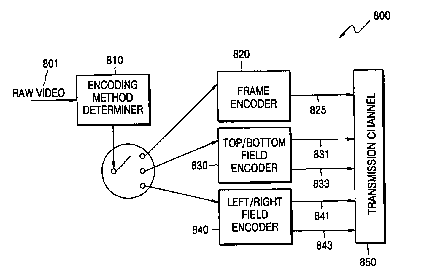
Video encoding and decoding methods and apparatuses are provided which are effective for error correction and error concealment in an error-prone environment. The video encoding method includes determining an encoding operation to encode raw video among a frame encoding operation, a top / bottom field encoding operation, and a left / right field encoding operation based on at least one characteristic of the raw video; and generating a bit stream by adaptively performing the encoding operation that is determined to encode the raw video. Further, video may be divided into frame pictures, top / bottom field pictures and left / right field pictures, and encoded accordingly. Therefore, a compression rate can be increased, and error correction and concealment can be effectively performed on a lost field by using a normally received field.

Description

CROSS REFERENCE TO RELATED APPLICATIONS [0001] This application claims priority from Korean Patent Application No. 10-2005-0061190, filed on Jul. 7, 2005, in the Korean Intellectual Property Office, the disclosure of which is incorporated herein in its entirety by reference. BACKGROUND OF THE INVENTION [0002] 1. Field of the Invention [0003] Apparatuses and methods consistent with the present invention relate to video encoding and decoding, and more particularly, to video encoding and decoding effective for error correction and error concealment in an error-prone environment. [0004] 2. Description of the Related Art [0005] The development of wireless Internet has rapidly increased the availability of bandwidth in a wireless environment. Accordingly, the amount of video image data that is provided in the wireless environment has consistently increased to meet the needs of users. Such an increase in the amount of video image data enhances visual quality and quality of service (QoS). H...

Claims


Application Information

Patent Timeline
IPC IPC(8): H04N11/02H04N19/12H04N19/137H04N19/89H04N19/196H04N19/33H04N19/50H04N19/503H04N19/577H04N19/59H04N19/60H04N19/61H04N19/625H04N19/895H04N19/91
CPCH04N19/139H04N19/159H04N19/46H04N19/36H04N19/112H04N19/114H04N19/37H04N19/89
Inventor RYU, KWANG-YUEL
Owner SAMSUNG ELECTRONICS CO LTD
Learn More