
Guide apparatus for mounting and dismounting inner part and image forming device having the same

Active Publication Date: 2007-01-11
HEWLETT PACKARD DEV CO LP
View PDF8 Cites 0 Cited by
  • Summary
  • Abstract
  • Description
  • Claims
  • Application Information

AI Technical Summary

Benefits of technology

[0013] An aspect of the present invention provides a guide apparatus to mount and dismount an inner part in an image forming device and an image forming device having the same installed therein where guide rails are integrally formed with a frame. Accordingly, aspects of the present invention realize easy manufacturing processes, reduce manufacturing costs and inferiorities, and increase the printing quality.
[0019] According to an aspect of the present invention, the horizontal guide surface includes an inclining part downwardly inclining toward the external of the frame, so that the corresponding first or second slider can easily move inside the frame, along the guide rails.
[0026] According to an aspect of the present invention, the horizontal guide surface includes an inclining part downwardly inclining toward the external of the frame, so that the corresponding first or second slider can easily move inside the frame, along the guide rails.

Problems solved by technology

Accordingly, manufacturing time and numbers of processes are increased, which leads to productivity deterioration and increases in manufacturing costs.
As such, the paper P, being counter-transmitted by the paper counter-transfer guiding part 62 in duplex printing operations, may suffer paper jams.
Accordingly, a crack caused by manufacturing faults in the fixing part may be worsened by repeated mounting and dismounting operations of the paper counter-transfer guiding part 62 with respect to the.
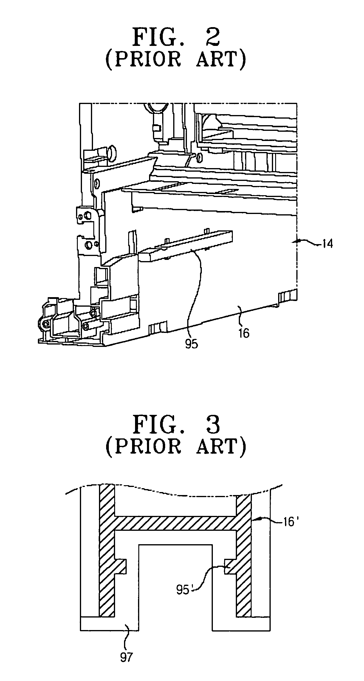
Also, the fixing parts may be damaged by shocks and as a result, escape from the first and the second side walls 16 or be forced away from the proper positions thereof, which may lead to malfunctions.

Method used


Image

  • Guide apparatus for mounting and dismounting inner part and image forming device having the same
  • Guide apparatus for mounting and dismounting inner part and image forming device having the same
  • Guide apparatus for mounting and dismounting inner part and image forming device having the same

Examples


Embodiment Construction

[0037] Reference will now be made in detail to the present embodiments of the present invention, examples of which are illustrated in the accompanying drawings, wherein like reference numerals refer to the like elements throughout. The embodiments are described below in order to explain the present invention by referring to the figures.

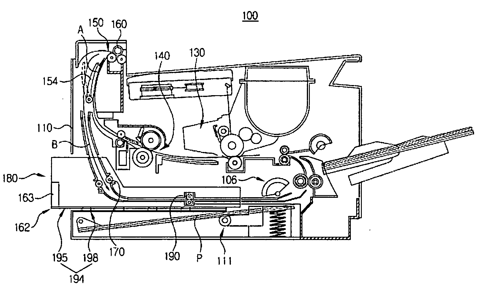
[0038]FIG. 4 schematically shows an image forming apparatus having a guide apparatus to allow for a mounting and dismounting of an inner part. The image forming apparatus having the guide apparatus may be a duplex printing laser printer 100 printing data received from an external device such as PC (personal computer).

[0039] As illustrated in FIG. 4, the duplex printing laser printer 100 includes: a paper supply cassette 111 that is mountable and dismountable to / from a frame 114 (FIG. 5) of a printer body 110, a picking-up and transferring unit 106 to pick up and transfer paper P loaded on the paper supply cassette 111; a developing unit 130 to form ...


PUM


Abstract

A guide apparatus for mounting and dismounting an inner part usable in an image forming device includes: a first and a second sliders formed at both sides of a built-in part respectively; a first and a second undercut preventing parts formed at a first and a second side walls of the frame facing the both sides of the inner part under the connecting member, respectively; and a first and a second guide rails integrally formed with the first and the second side walls adjacent to the first and the second undercut preventing parts, respectively, and housing and guiding the first and the second sliders. Accordingly, the first and the second guide rails are integrally formed with the first and the second side walls of the frame, respectively, so that manufacturing is simpler, manufacturing costs and inferiority are reduced, and the intensity is increased.

Description

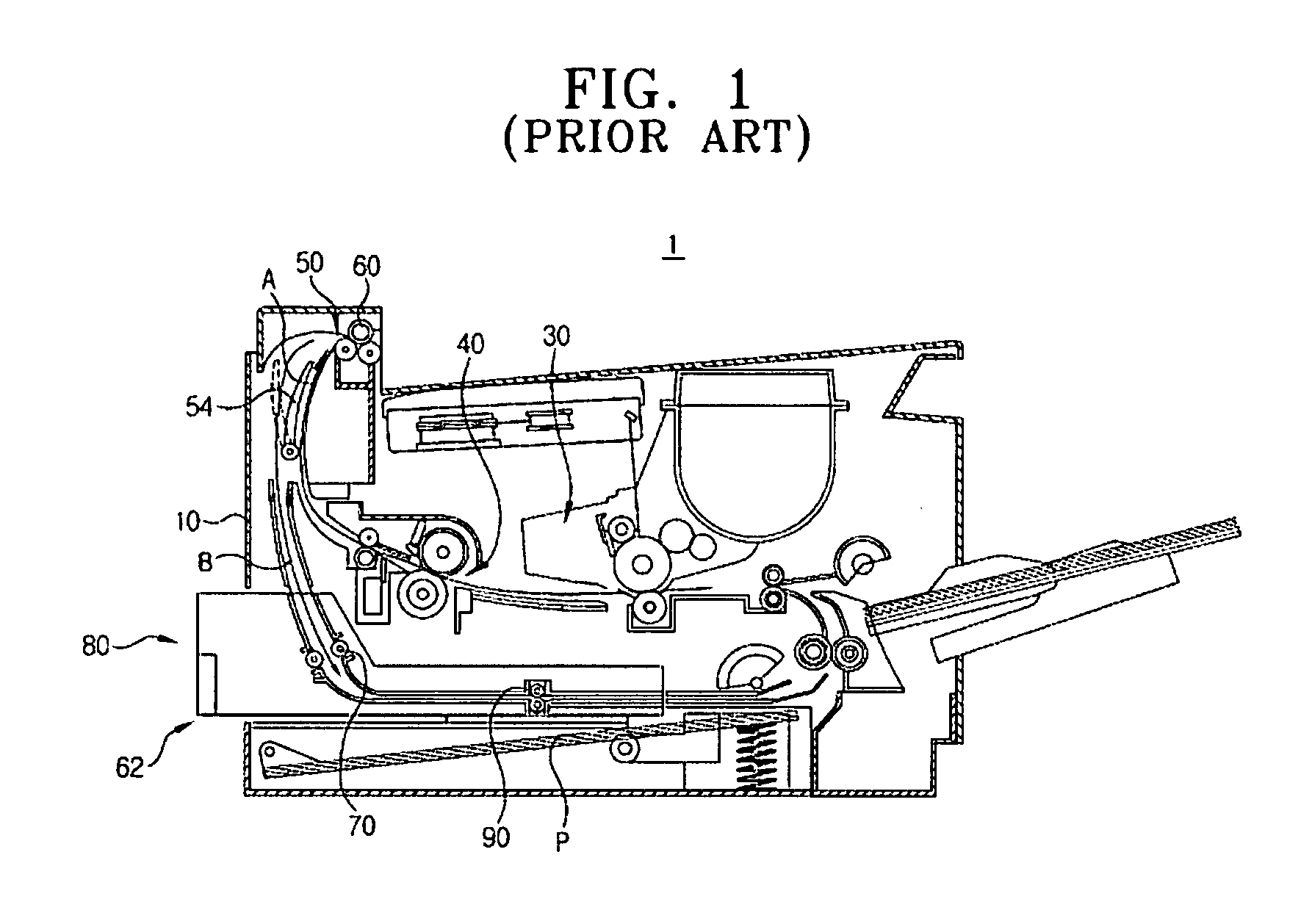
CROSS-REFERENCE TO RELATED APPLICATION [0001] This application claims the benefit under 35 U.S.C. § 119(a) of Korean Patent Application No. 2005-57212, filed Jun. 29, 2005 in the Korean Intellectual Property Office, the disclosure of which is incorporated herein by reference. BACKGROUND OF THE INVENTION [0002] 1. Field of the Invention [0003] Aspects of the present invention relate to an image forming apparatus such as a laser printer and a duplicator. More particularly, aspects of the present invention relate to a guide apparatus for mounting and dismounting an inner part such as a paper counter-transfer guiding part of a duplexed printing unit with respect to a frame of a device body and an image forming device having the same. [0004] 2. Description of the Related Art [0005] Generally, a duplex printing image forming apparatus, for example, a duplex printing laser printer 1, as illustrated in FIG. 1, includes a duplex printing unit 80 that re-inserts paper P, having one side alrea...

Claims


Application Information

Patent Timeline
IPC IPC(8): B41J29/02
CPCB41J29/02B41J3/60G03G15/00G03G21/1623G03G21/1647
Inventor EOM, TAE-WON
Owner HEWLETT PACKARD DEV CO LP
Learn More