Air hole structure on relay shell

A relay and ventilation hole technology, which is applied in the directions of relay ventilation/cooling/heating, relay base/shell/cover, etc., can solve the problems of easy blockage of the outer end of the ventilation hole, difficult molding technology, and technical difficulty, etc. Reduce the difficulty of manufacturing molding technology, reliable molding, and good economic effects

Pending Publication Date: 2021-01-26
SICHUAN HONGFA ELECTROACOUSTIC
View PDF3 Cites 3 Cited by
  • Summary
  • Abstract
  • Description
  • Claims
  • Application Information

AI Technical Summary

Problems solved by technology

Although these technical measures are relatively effective in solving the technical problem that pollutants directly invade the inside of the relay housing through the vent hole, they are easy to block the outer end of the vent hole, especially when the conformal paint is applied during the PCB forming process. The technical problem that the outer end of the hole is easy to be blocked has not been effectively solved; moreover, the ventilation holes of the air passage bending structure formed on the relay housing by these technical measures have the technical problems of difficult molding technology and high cost. Because the mold design process of the relay housing with such a vent structure is very difficult and even impossible to realize. Hole to achieve high efficiency, high pass rate of production control

Method used


Image

  • Air hole structure on relay shell
  • Air hole structure on relay shell
  • Air hole structure on relay shell

Examples


Embodiment 1

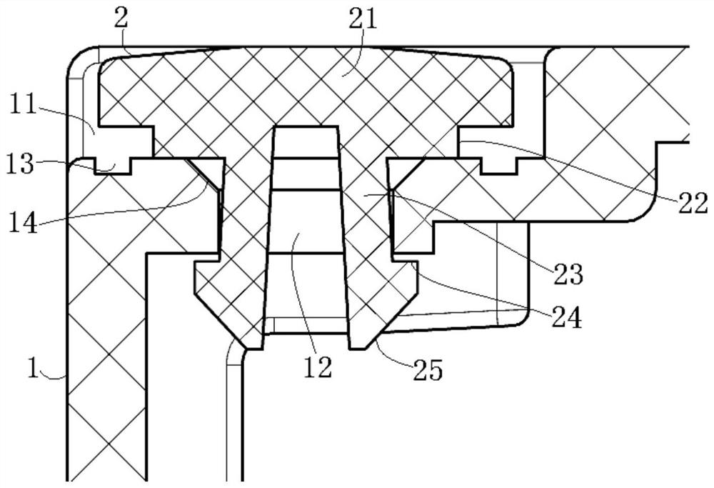
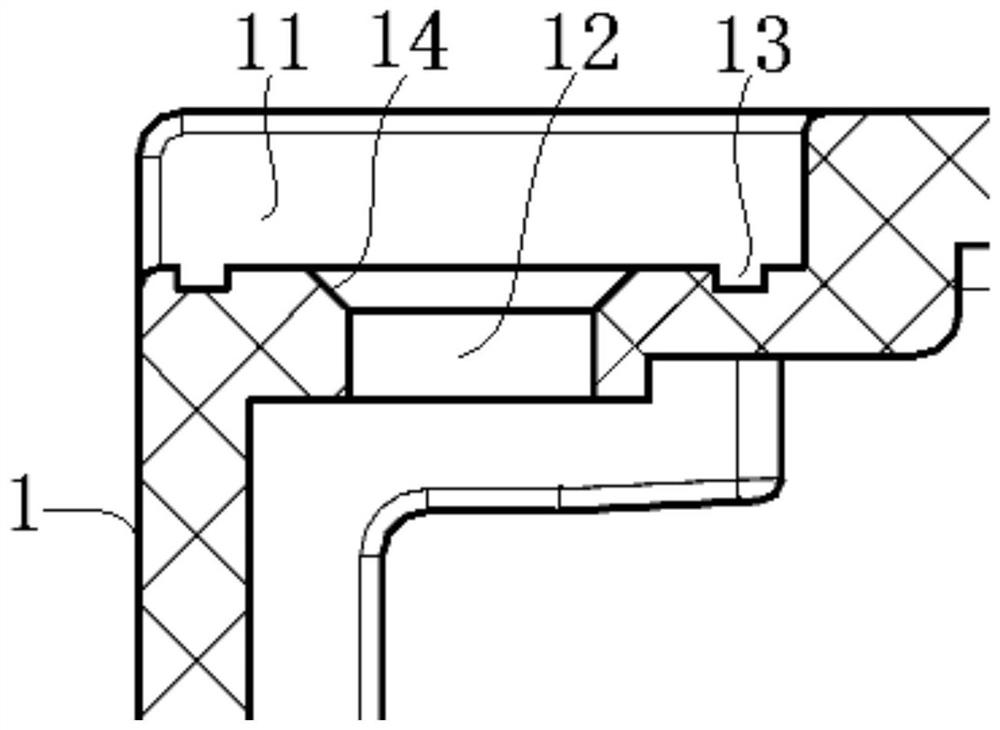
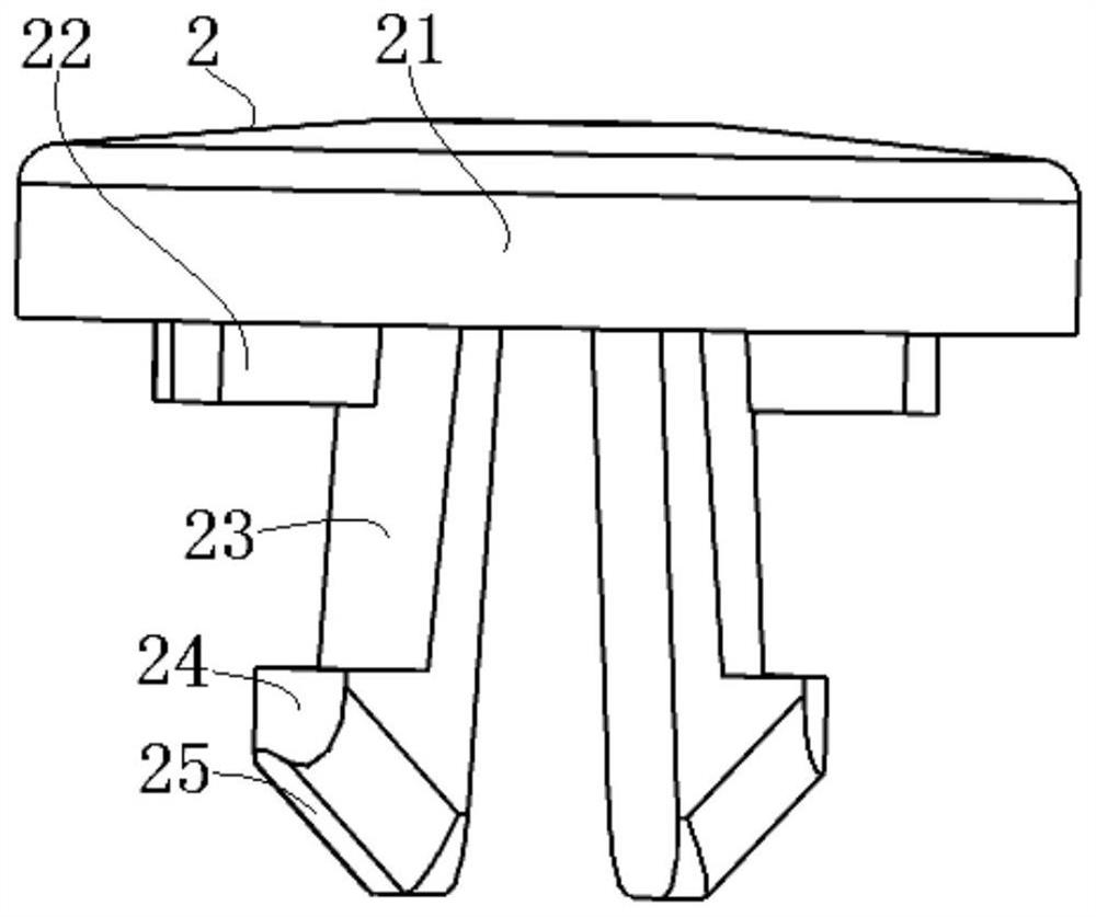
[0030] see figure 1 , figure 2 and image 3 As shown, the present invention is a vent structure on the relay housing, which includes a base hole 12 formed on the relay housing 1 that can communicate with the inside and outside of the housing, and an expansion card that can be assembled in the base hole 12 Plug 2.

[0031]Specifically, one corner of the relay housing 1 is used as the forming area of ​​the base hole 12, and the outer surface of this area has a concave cavity 11 for forming the base hole 12. The depth of the cavity 11 should correspond to the The top of the expansion plug 2 is substantially flush with or slightly lower than the outer surface of the current board of the relay housing 1, and the area of ​​the cavity 11 should be larger than the area of ​​the plug cap 21 of the expansion plug 2. Since the concave cavity 11 is formed at a corner of the relay housing 1, the outer peripheral walls on both sides of the concave cavity 11 are open structures, that is,...

Embodiment 2

[0045] The invention relates to a vent hole structure on a relay housing, which includes a base hole formed on the relay housing that can communicate with the inside and outside of the housing, and an expansion plug that can be assembled in the base hole.

[0046] Specifically, one corner of the relay housing is used as the forming area of ​​the base hole, and the outer surface of this area has a concave cavity for forming the base hole. The depth of the cavity should correspond to the top of the assembled expansion plug It is basically flush with or slightly lower than the outer surface of the current board of the relay housing, and the area of ​​the concave cavity should be larger than the area of ​​the plug cap of the expansion plug. Since the concave cavity is formed at one corner of the relay casing, the outer peripheral walls at the two sides of the concave cavity are open structures, that is, the corner of the current plate of the relay casing is a stepped surface struct...

Embodiment 3

[0060] The other contents of this embodiment are the same as those of Embodiment 1 or Embodiment 2, except that there is no dirt collection tank structure on the relay housing.

[0061] Under this technical measure, in order to effectively prevent the intrusion of pollutants, it is best to design the plug cap of the expansion plug large enough, so that the air passage at the outer end of the base hole (that is, the bottom surface of the plug cap and the relay) The air passage formed between the shell surfaces) is long enough to counteract the kinetic force of the pollutant intrusion.


PUM


Abstract

The invention discloses an air hole structure on a relay shell. The structure comprises a base hole formed in the relay shell and capable of communicating the inside with the outside of the shell, anda plug capable of shielding the outer end part of the base hole is assembled in the base hole on the relay shell. The plug is matched with the base hole, so that an air hole of which the air passageis of a non-straight passage structure is formed in the relay shell. Pollutants can be effectively prevented from directly intruding into the relay shell through the air holes, the air channel is notprone to being blocked, and the relay shell can be manufactured and formed in a simple, easy and economical mode.

Description

technical field [0001] The invention relates to a component part of a relay-a casing, in particular to a vent hole structure on the relay casing. Background technique [0002] In order to balance the internal and external air pressure of the relay case in the application condition, a vent hole that can communicate with the interior and exterior of the case is formed on the relay case, which is especially suitable for solder-proof relays used in high-temperature environments. universal. [0003] Due to the small size of the relay itself and the strict technical requirements for electrical performance, the diameter of the vent holes formed on the relay housing is usually about 1mm, which is reflected in the small or ultra-small solder-proof relays used in household appliances. most direct. Such fine air holes are usually formed on the relay housing with a straight hole structure during casting. [0004] However, due to the existence of the straight hole structure air holes ...

Claims


Application Information

Patent Timeline
Patent Type & Authority Applications(China)
IPC IPC(8): H01H45/02H01H45/12
CPCH01H45/02H01H45/12
Inventor 陈崇善徐勇
Owner SICHUAN HONGFA ELECTROACOUSTIC
Why Eureka
Try Eureka