Hand grinder, flange for accomodating a grinding tool, and balancing unit

a technology for balancing units and power grinders, which is applied in the direction of manufacturing tools, mechanical equipment, and portable power-driven tools. it can solve problems such as annoyance to users, and achieve the effects of reducing vibration, balancing the working shaft and the grinding tool reliably, and reducing the vibration of the handheld power grinder

Inactive Publication Date: 2007-01-11
ROBERT BOSCH GMBH
View PDF12 Cites 7 Cited by
  • Summary
  • Abstract
  • Description
  • Claims
  • Application Information

AI Technical Summary

Benefits of technology

[0004] The invention is based on a handheld power grinder, having a motor located in a housing, having a receiving flange receiving a grinding tool, and having a motor-driven working shaft as well as a balancing unit that has at least one first and one second balancing mass.
[0005] It is proposed that the first balancing mass is embodied as a movable balancing mass, and the second balancing mass is embodied as a fixed balancing mass. The movable balancing mass, with the working shaft rotating, can move into a balancing position, while the fixed balancing mass forms a structural unit with the balancing unit and maintains its position in which it was installed. If an imbalance changes, then the movable balancing mass can adapt at least partially, while the fixed balancing mass remains in the installed position. Advantageously, given a change in the imbalance over time from progressive wear and tear of the grinding tool, this makes it possible to balance a working shaft and the grinding tool reliably, even over long-term use. This is because for the same balancing capacity of the fixed and movable balancing masses, for instance, twice as much balancing capacity can be handled by subtraction or addition as by a single movable balancing unit, yet that unit requires just as much installation space. Moreover, the combination of fixed and movable balancing masses makes a compact arrangement possible. Any vibration that occurs in the handheld power grinder is lessened, making the handheld power grinder more comfortable to use.
[0006] If the movable first balancing mass is formed by balls guided in a race, then they form an especially smooth-running movable balancing mass. When the working shaft is rotating, the balls automatically move into the balancing position and thus automatically achieve balancing. The balancing position is adapted automatically whenever conditions change. The adaptation takes place very quickly, since static friction of the balls is negligible. One or more races may be provided concentrically to an axis of rotation. Alternatively, rings may be provided, which move along one or more cylindrical surfaces that are concentric to the axis of rotation.
[0007] If the fixed second balancing mass is formed by a balancing sector that forms part of the circumference of the balancing unit, then a proportion of the imbalance can be compensated for.
[0008] If the receiving flange for a grinding tool has a grinding tool receptacle that is eccentric to an axis of rotation, then increased material can be removed by grinding, with simultaneous compensation of vibration and improved convenience of use of the handheld power grinder. Thus in a conventional handheld power grinder, an eccentricity of the grinding tool motion advantageously increases the grinding abrasion just as much as is the case in eccentric power grinders that are designed especially for eccentric operation.
[0009] If the receiving flange is a component of the balancing unit, a compact structural unit is created that can easily be built into handheld power grinders and can easily be replaced or retrofitted as needed.

Problems solved by technology

In a handheld power grinder, for instance, rotating structural units whose common center of gravity is not located in the axis of rotation are the source of vibration, which is quite annoying to a user, and to compensate for which balancing systems are employed.

Method used


Image

  • Hand grinder, flange for accomodating a grinding tool, and balancing unit
  • Hand grinder, flange for accomodating a grinding tool, and balancing unit
  • Hand grinder, flange for accomodating a grinding tool, and balancing unit

Examples


Embodiment Construction

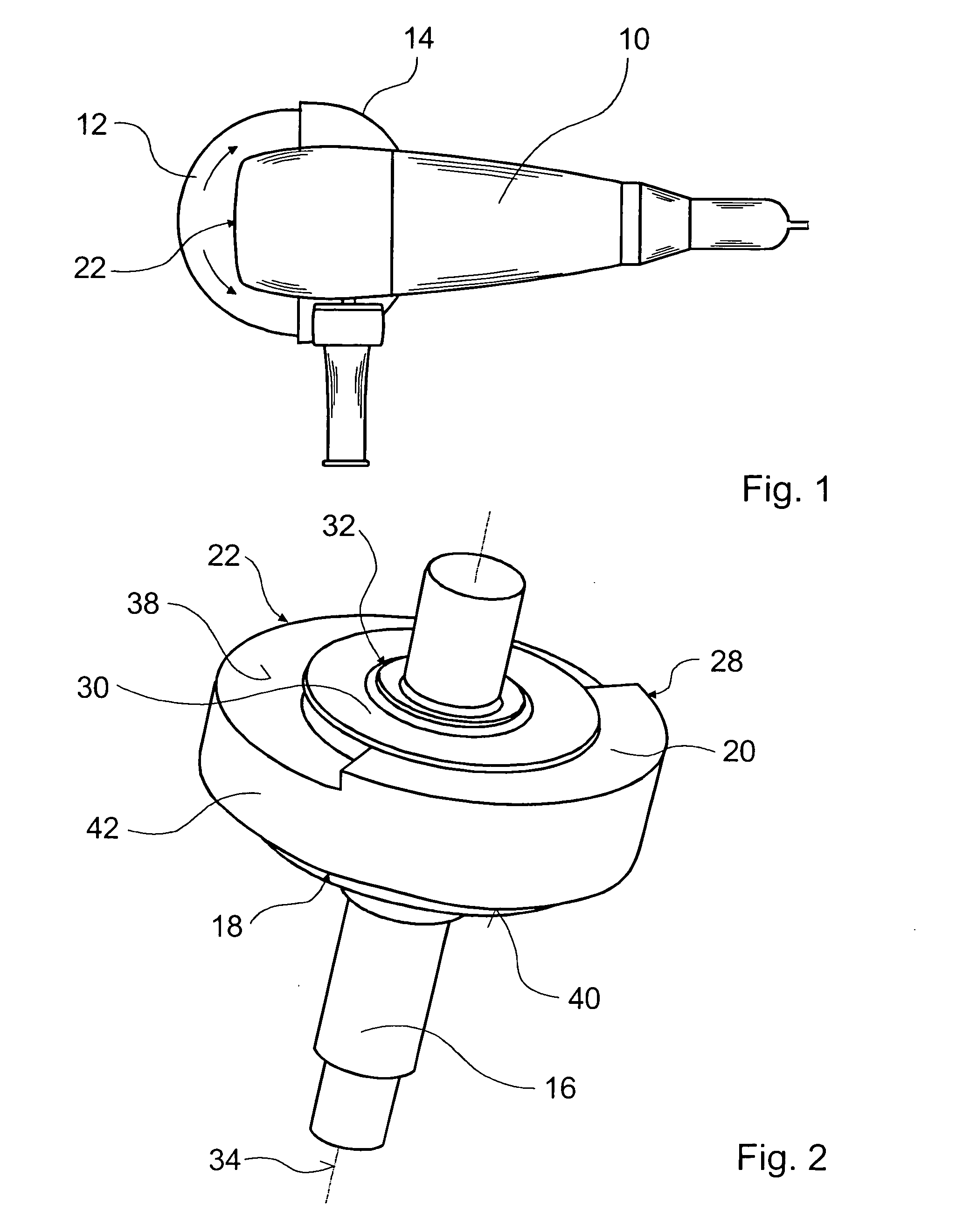
[0031]FIG. 1 shows a preferred handheld power grinder in a top view with a motor located in a housing 10, with a grinding tool 12 which is connected to a motor- driven working shaft, not shown, and with a balancing unit 22, which will be described in further detail in conjunction with the ensuing drawings. In the drawings, identical elements are identified by the same reference numerals throughout. The grinding tool 12, in this case a grinding wheel, may be covered with a guard hood 14, to protect a user from injuries.

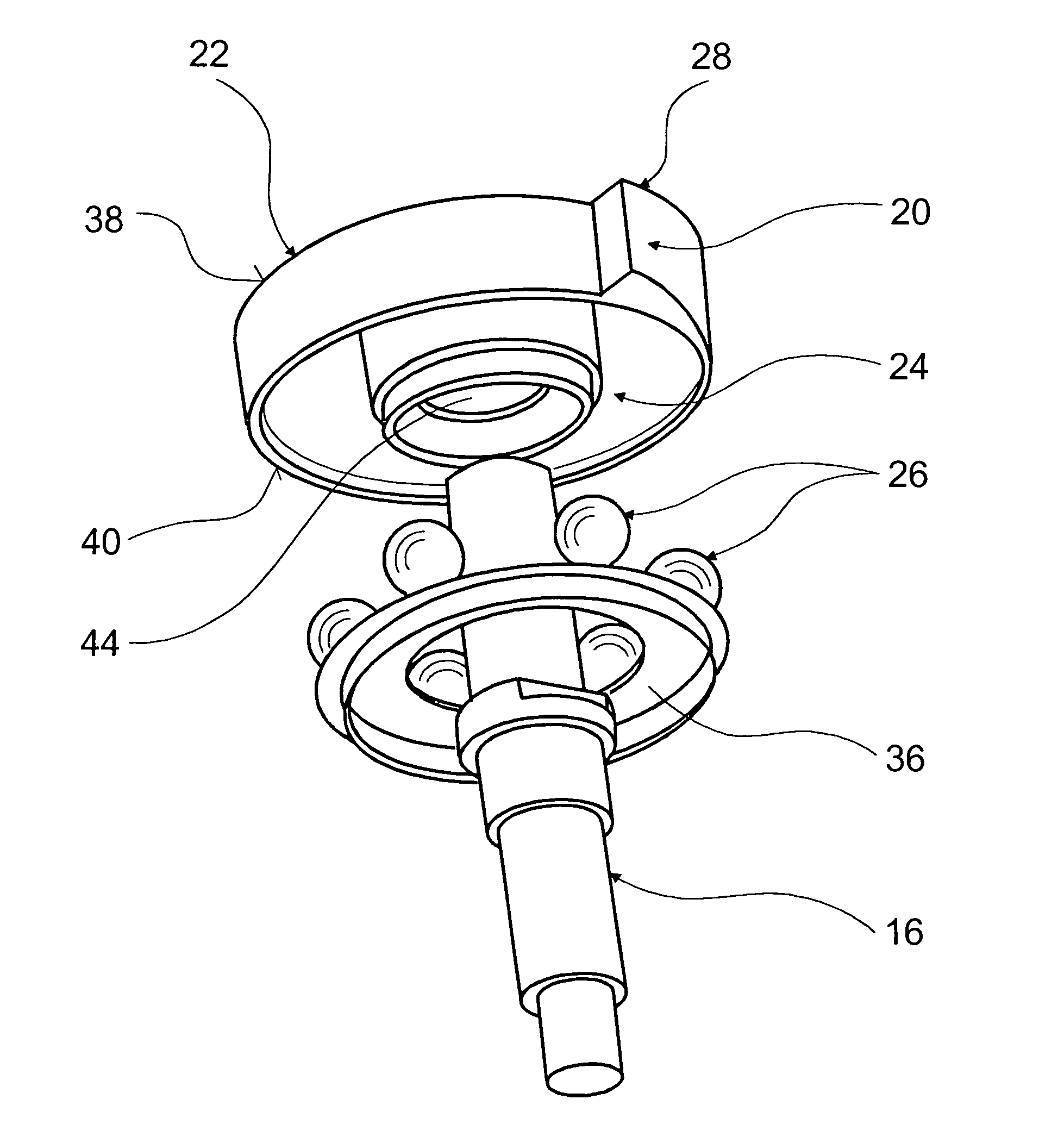
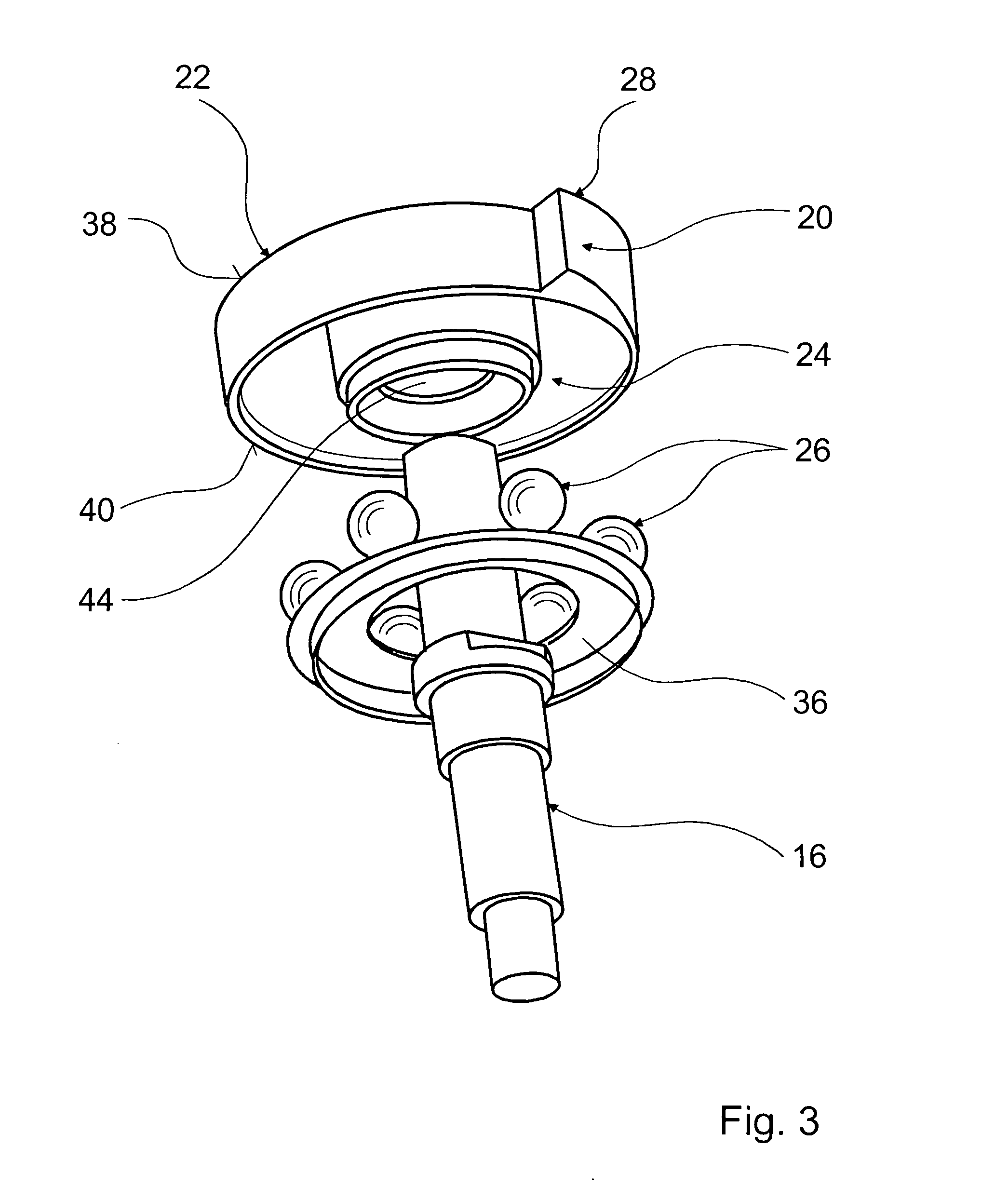
[0032] A detail of the arrangement of the balancing unit 22 is shown in FIG. 2. On a working shaft 16 which is driven by the motor, not shown, in particular an electric motor, the balancing unit 22 is seated concentrically with a receiving flange 30, which is integrated a front side 38 and has an eccentrically embodied grinding tool receptacle 32 for the grinding tool 12. The working shaft 16 rotates about the axis of rotation 34. The balancing unit 22 has both a fixe...


PUM


Abstract

The invention is based on a handheld power grinder, having a motor located in a housing (10), having a receiving flange (30) receiving a grinding tool (12), and having a motor-driven working shaft (16) as well as a balancing unit (22) that has at least one first and one second balancing mass (18, 20).
It is proposed that the first balancing mass is embodied as a movable balancing mass (18), and the second balancing mass is embodied as a fixed balancing mass (20). A receiving flange for a grinding tool (12) and a balancing unit are also proposed.

Description

PRIOR ART [0001] The invention is based on a handheld power grinder, a receiving flange for a grinding tool, and a balancing unit as generically defined by the preambles to the independent claims. [0002] In a handheld power grinder, for instance, rotating structural units whose common center of gravity is not located in the axis of rotation are the source of vibration, which is quite annoying to a user, and to compensate for which balancing systems are employed. However, without compensation the grinding progress is greater than with compensation. [0003] German Patent Disclosure DE 196 17 478 has already proposed a handheld power grinder in which two balancing masses are used that are offset from one another in the axial direction of a working shaft. The balancing masses are located on the working shaft in the interior of the housing of the handheld power grinder between two rotary bearings. ADVANTAGES OF THE INVENTION [0004] The invention is based on a handheld power grinder, havin...

Claims


Application Information

Patent Timeline
Patent Type & Authority Applications(United States)
IPC IPC(8): B24B41/00B23Q11/00B24B23/00B24B41/04B24D5/16B25F5/00F16F15/36
CPCB23Q11/0035B24B23/00B24B41/007F16F15/363B24D5/165F16F15/36B24B41/042
Inventor LAMPRECHT, JUSTUS
Owner ROBERT BOSCH GMBH
Why Eureka
Try Eureka