Placement methods for standard cell library

a cell library and placement method technology, applied in the field of semiconductor devices and their manufacture, can solve the problems of high or low threshold voltage (vt) transistors in standard cell library inefficient use of area, manufacturing difficulties, and macros with severe placement restrictions

Active Publication Date: 2007-01-11
TEXAS INSTR INC
View PDF26 Cites 29 Cited by
  • Summary
  • Abstract
  • Description
  • Claims
  • Application Information

AI Technical Summary

Problems solved by technology

Problematically, standard cell library macros with high or low threshold voltage (Vt) transistors can be inefficient in their use of area.
Also, the macros often have severe placement restrictions in an ASIC backplane.
These inefficiencies are partly due to the design rules required to enable implant mask generation and subsequent use in a silicon fabrication process.
Features within the layout 10 that are not suitable for reproduction in a mask, such as the intersecting corners indicated at 12, create manufacturing difficulties.
Although useful in preventing particular errors, this prior art approach leaves much to be desired in terms of efficient use of area.

Method used


Image

  • Placement methods for standard cell library
  • Placement methods for standard cell library

Examples


Embodiment Construction

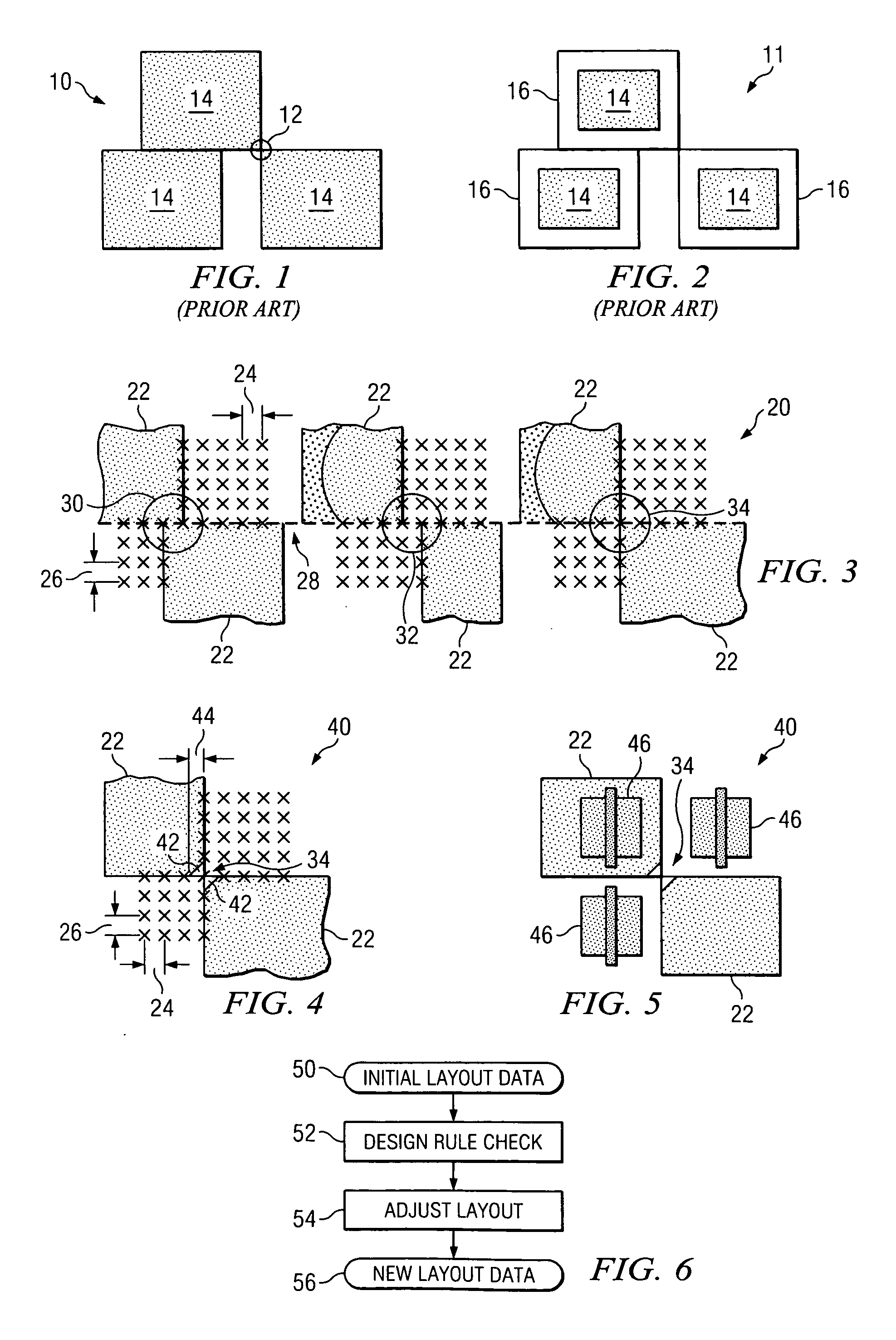
[0018]FIG. 3 is a schematic diagram of a layout 20 useful for the purposes of describing the invention. The layout 20 includes macros 22 containing specific circuit elements, the details of which are not material to the practice of the invention. The macros 22 are arranged in a grid pattern with (x, y) coordinates having fixed dimensions, indicated by arrows 24, 26. Typically, the macros 22 are arranged in rows, in this example adjoining at line 28, subject to design rules. It will be appreciated by those reasonably skilled in the arts that the invention may be practiced with a wide range of dimensions and design rules and that the description herein is exemplary and not exclusive. As shown at location 30, macros 22 in adjacent rows may intersect in certain instances at row boundaries 28 so long as minimum (x, y) dimensions are maintained. At location 32, it is shown that separation of macros 22 at the boundary 28 of adjacent rows is also acceptable, again, so long as suitable (x, y...


PUM


Abstract

Methods are disclosed for the layout and manufacture of microelectronic circuits. The methods employ the monitoring of the placement of macros within circuit layouts for design rule compliance. Upon detection of noncompliance, the macros associated with noncompliance are adapted to bring the layout within the design rules. In a preferred embodiment of the invention monitoring the relative positions of macros includes identifying instances of coinciding macro (x, y) coordinates. Adapting noncompliant macros further includes steps for maintaining minimum (x, y) distances between adjacent macro corners.

Description

TECHNICAL FIELD [0001] The invention relates to semiconductor devices and their manufacture. More particularly, the invention relates to methodology for laying out microelectronic circuitry in compliance with selected design restrictions. BACKGROUND OF THE INVENTION [0002] Integrated circuit designers constantly strive to make the individual features within integrated circuits smaller so that the device density of the overall system can be improved. The ultimate size of devices in an integrated circuit is affected by the ability to create the photo mask used to implement the designed features, and by the ability to reproduce the masked features in the finished circuit. Typically, a standard cell library of macros for individual features is used to lay out the circuit. Various design rules are used to regulate the interactions among the macros. Problematically, standard cell library macros with high or low threshold voltage (Vt) transistors can be inefficient in their use of area. Al...

Claims


Application Information

Patent Timeline
Patent Type & Authority Applications(United States)
IPC IPC(8): G06F17/50
CPCG06F17/5072G06F30/392
Inventor PITTS, ROBERT L.
Owner TEXAS INSTR INC
Why Eureka
Try Eureka