Method, bar blade, and use thereof for milling spiral bevel gears and hypoid gears
a technology of spiral bevel gears and bar blades, which is applied in the direction of gear teeth, gear manufacturing apparatus, manufacturing tools, etc., can solve the problems of reduced wear of individual bar cutting blades and subjected to wear phenomena in the complete profile entering the tooth slot, so as to improve the useful life of cutting blades. the effect of considerable improvemen
- Summary
- Abstract
- Description
- Claims
- Application Information
AI Technical Summary
Benefits of technology
Problems solved by technology
Method used
Image
Examples
third embodiment
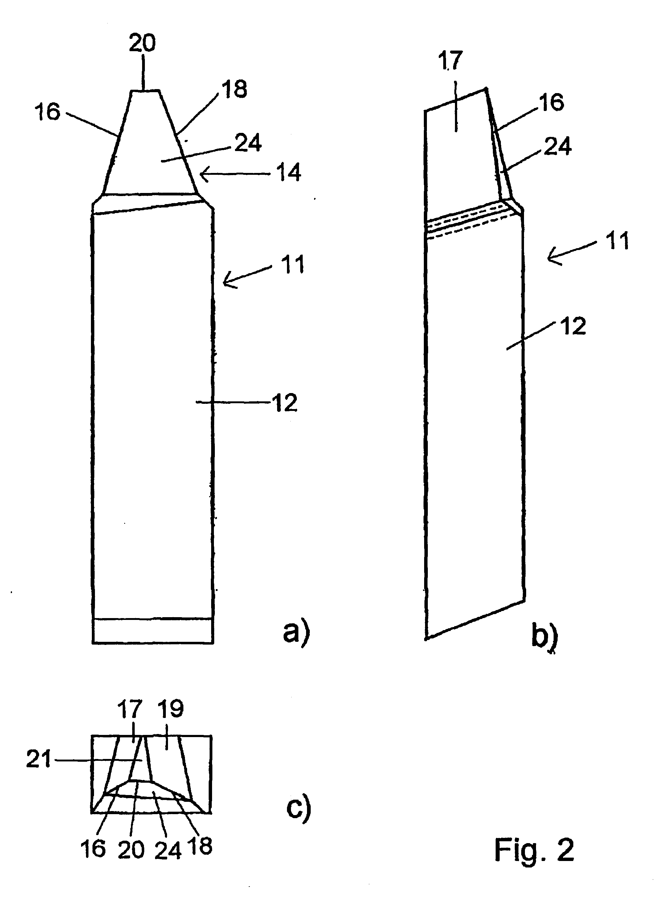
[0063] FIGS. 7 AND 8 show as the bar cutting blade of the invention the triplex flank ground or profile-sharpened and form-ground bar cutting blade 11 with the rake surface 24 to be reground in a front view (FIG. 7) and in a top plan view (FIG. 8). In contrast to the embodiment of FIGS. 4-6 which shows the general case regarding the orientation of the rake surface 24, the embodiment of FIGS. 7 AND 8 relates to the special case in which the rake surface 24 is oriented in such manner that the two cutting edges 16 and 18 are in a symmetrical relationship to each other resulting in like rake angles Ys (illustrated in FIG. 11c).
[0064] In the bar cutting blade 11 of FIGS. 7 AND 8 the rake angle Ys differs from the rake angle of the bar cutting blade 11 of FIGS. 4-6, being measured according to the representation of FIGS. 11a-f to be discussed in greater detail further below between the rake surface and a reference plane B of the cutting edge (cf., for example, the representation of FIG. 1...
fourth embodiment
[0065] FIGS. 9 AND 10 show as the bar cutting blade of the invention the triplex flank ground or profile-sharpened and form-ground bar cutting blade 11 with a rake surface 26 to be reground in a front view (FIG. 9) and in a top plan view (FIG. 10). In contrast to the other embodiments, the rake surface 26 between the first and second cutting edges 16, 18 is curved in a concave configuration. In this case both cutting edges 16, 18 result in a positive rake angle.
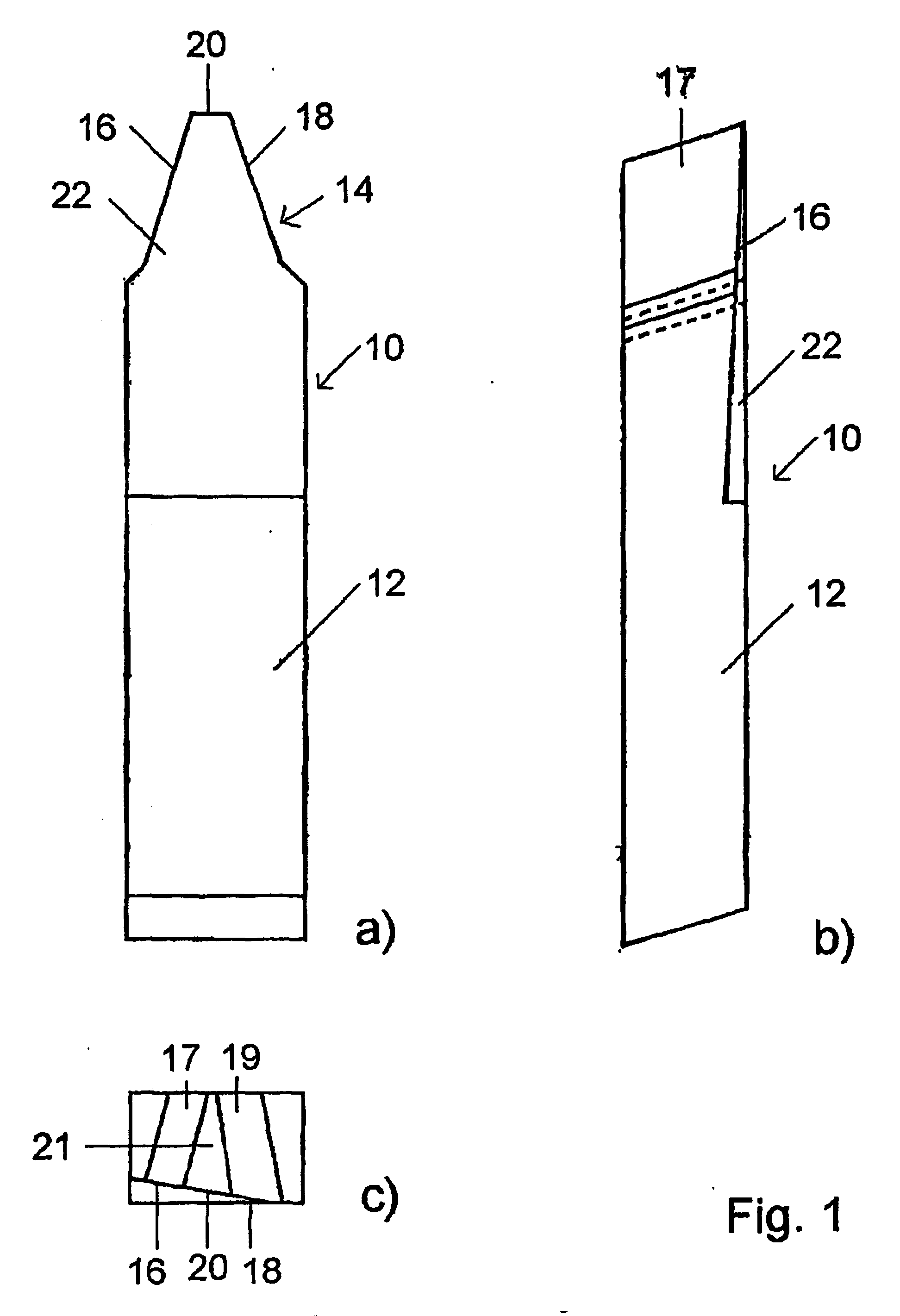
[0066]FIGS. 11a-f show the size and the position of the rake angles YS for different embodiments of the bar cutting blade of the invention, i.e., in FIG. 11a for the bar cutting blade 10 of FIGS. 1-3, in FIG. 11b for the bar cutting blade 11 of FIGS. 4-6, in FIG. 11c for the bar cutting blade 11 of FIGS. 7 and 8, in FIG. 11d for the bar cutting blade 11 which, while corresponding to FIGS. 4-6, has its rake surface 24 angled in inverted position relative to the reference plane B, in FIG. 11e for the bar cutting blade 11 of FIG...
PUM
| Property | Measurement | Unit |
|---|---|---|
| Pressure | aaaaa | aaaaa |
| Angle | aaaaa | aaaaa |
Abstract
Description
Claims
Application Information
 - R&D
- Intellectual Property
- Life Sciences
- Materials
- Tech Scout
- Unparalleled Data Quality
- Higher Quality Content
- 60% Fewer Hallucinations
Browse by: Latest US Patents, China's latest patents, Technical Efficacy Thesaurus, Application Domain, Technology Topic, Popular Technical Reports.
© 2025 PatSnap. All rights reserved.Legal|Privacy policy|Modern Slavery Act Transparency Statement|Sitemap|About US| Contact US: help@patsnap.com


