
Laser alignment device

a laser alignment and laser technology, applied in the field of laser alignment devices, can solve the problems of unsteady locating or disengagement, trouble, and loss of stability, and achieve the effect of convenient disassembly

Inactive Publication Date: 2007-01-18
CHEN MING
View PDF5 Cites 16 Cited by
  • Summary
  • Abstract
  • Description
  • Claims
  • Application Information

AI Technical Summary

Benefits of technology

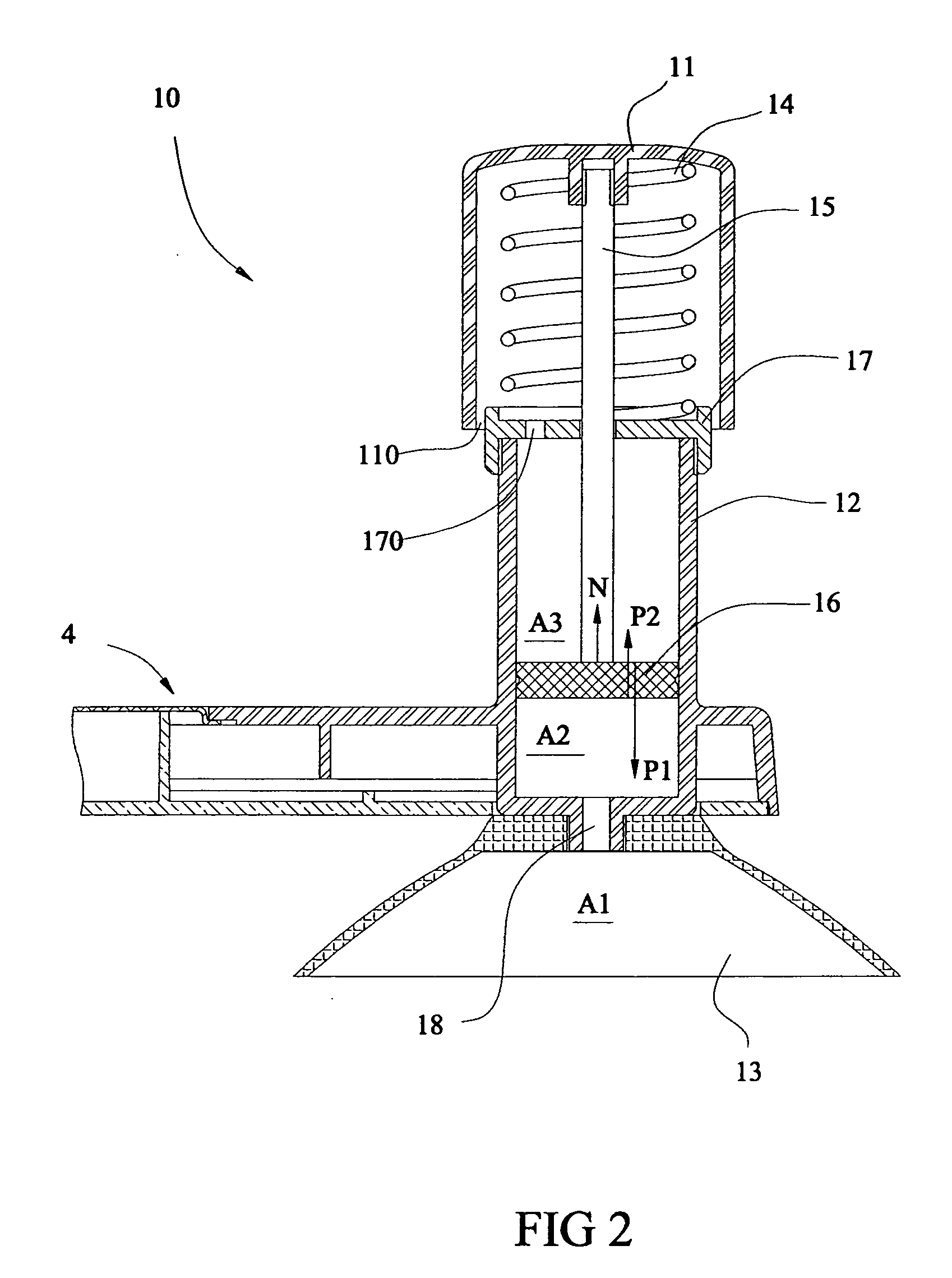
[0010] There are multiple advantages by using the above fixing means for the laser alignment device. Firstly, the fixing means using the suction cup will not damage the wall surface. Secondly, while under action of the spring, the piston can move in the cylinder to automatically and efficiently maintain the air pressure in the suction cup within a more constant range so that the suction force can be kept balance for a longer time period, thereby the laser alignment device can be fixed on the wall surface for a long time period, and trouble due to unsteady locating or disengagement is diminished.
[0013] With the combination of the body and the base of the laser alignment device having magnetic attraction, the body can be easily disassembled from the base and be displaced to various types of bases to meet requirements of different working surfaces.

Problems solved by technology

Secondly, while under action of the spring, the piston can move in the cylinder to automatically and efficiently maintain the air pressure in the suction cup within a more constant range so that the suction force can be kept balance for a longer time period, thereby the laser alignment device can be fixed on the wall surface for a long time period, and trouble due to unsteady locating or disengagement is diminished.

Method used


Image

  • Laser alignment device
  • Laser alignment device
  • Laser alignment device

Examples


Embodiment Construction

[0018] While this invention is susceptible of embodiments in many different forms, there is shown in the drawings and will herein be described in detail preferred embodiments of the invention with the understanding that the present disclosure is to be considered as an exemplification of the principles of the invention and is not intended to limit the broad aspect of the invention to the embodiments illustrated.

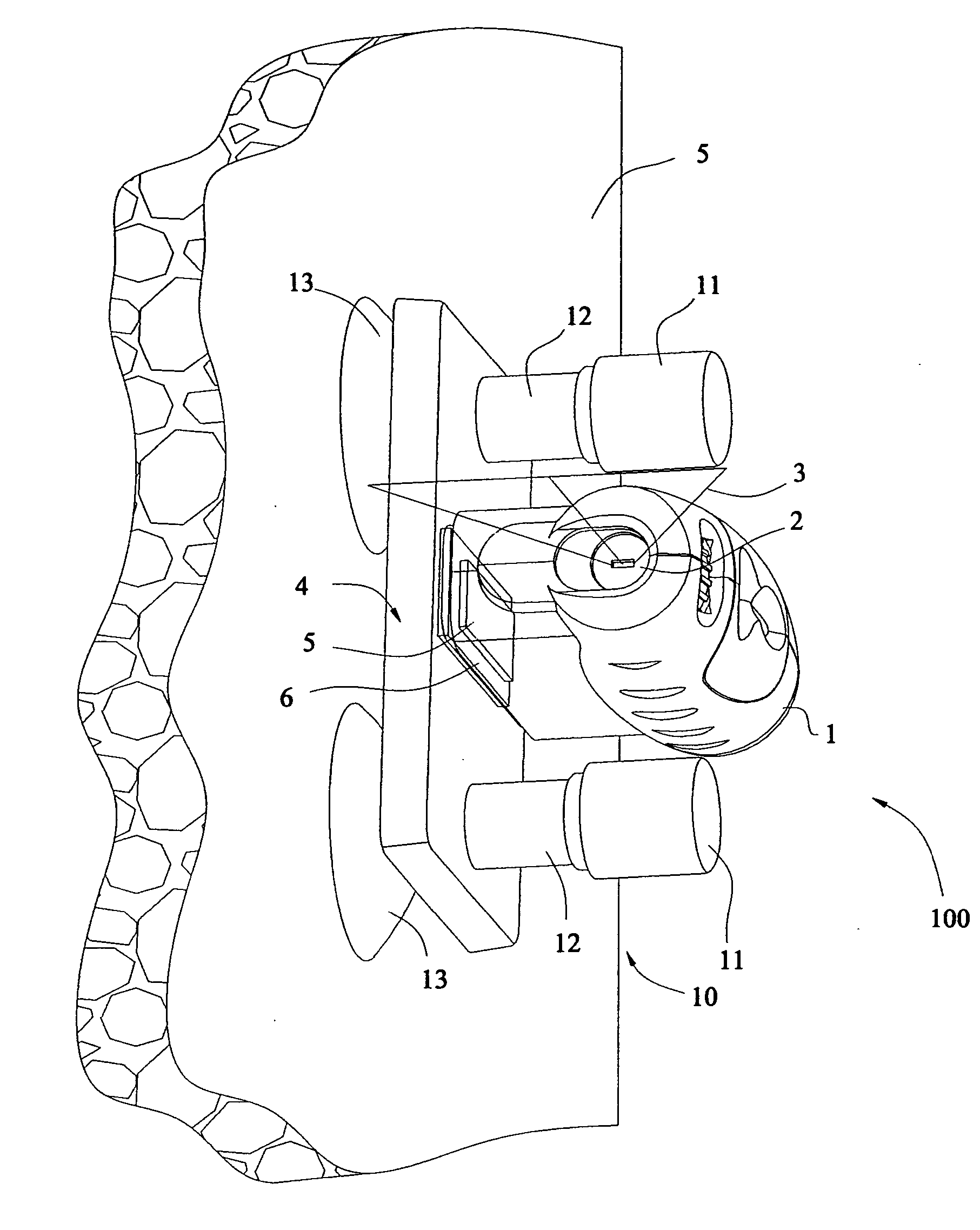
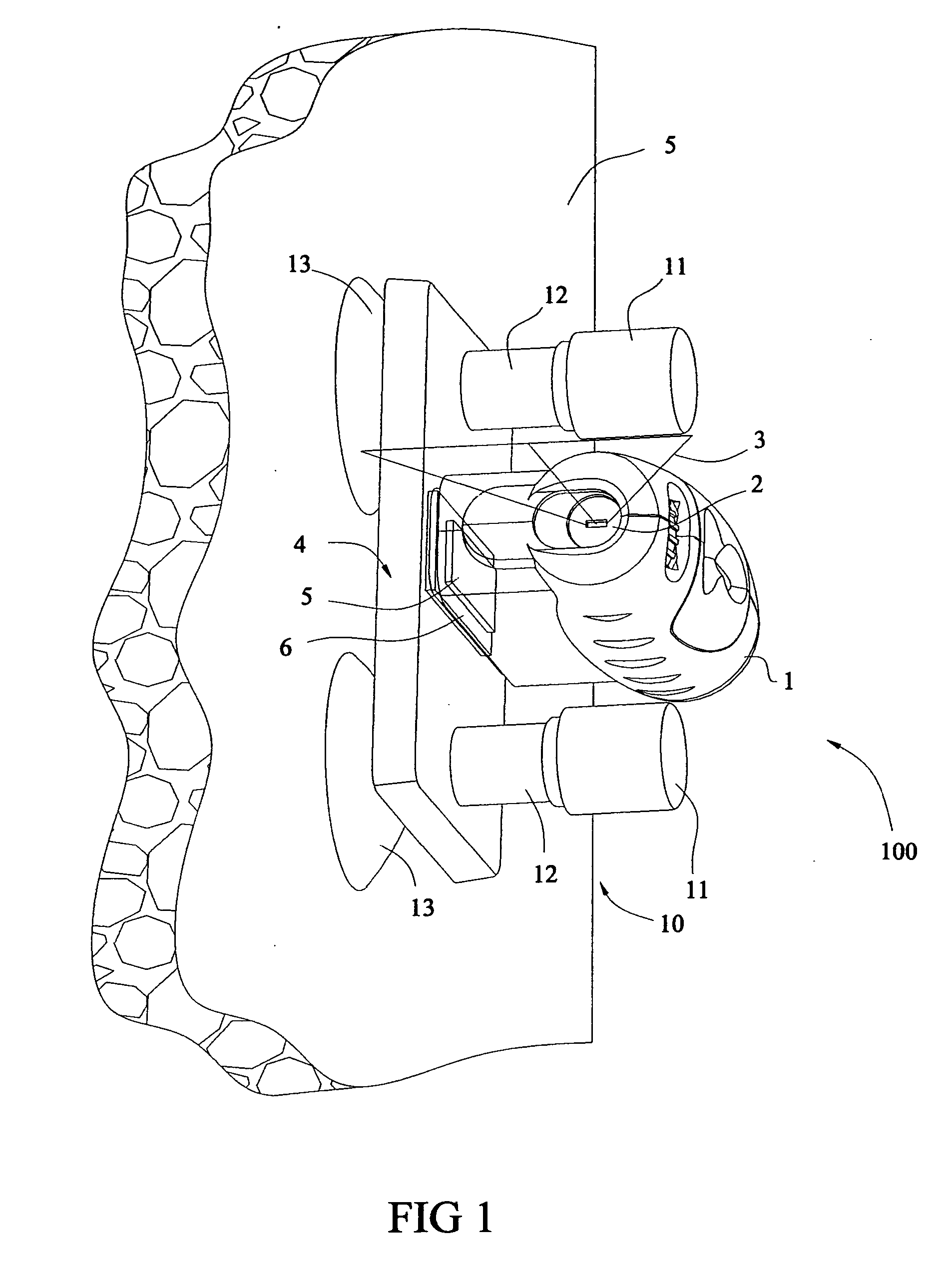
[0019] As shown in FIG. 1, a laser alignment device 100 comprises a body 1 and a base 4, a laser emitter 2 is provided in the body 1 and may emit a fan-shaped beam 3. The body I is provided with a bottom magnet 5, and the base 4 is provided with a magnet-attractive mass 6 which may be made of material attractive with magnet such as magnet or iron and the like. The body 1 is coupled with the base 4 by the attraction of the bottom magnet 5 and the magnet-attractive mass 6. A fixing means 10 is provided in each of two ends of the base 4. The body 1 and the base 4 are fixed toget...


PUM


Abstract

A laser alignment device is disclosed according to the present invention, which may emit a laser beam and form one or more reference lines on an object surface. The laser alignment device, comprising a body in which a laser emitter is provided, the body is connected with a base that includes a fixing means. The laser alignment device is sucked onto the surface of the object by a suction cup. The suction cup is connected to a cylinder further comprising a piston which may slide therein due to a spring means so that the suction force of the suction cup can be adjusted. This laser alignment device does not cause any damage when fixed onto a wall surface. The fixing means has a strong suction force and may fix the laser alignment device onto the wall surface for a long time, and thus the trouble due to unsteady position or disengagement in operation is reduced.

Description

CROSS-REFERENCE TO RELATED APPLICATIONS [0001] This application claims priority to Chinese Application No. 200520073680.6, filed on Jul. 18, 2005, the entire disclosure of which is incorporated herein by reference. Priority to this application is claimed under 35 U.S.C. 119, 120 and / or 365. FEDERALLY SPONSORED RESEARCH OR DEVELOPMENT [0002] None. TECHNICAL FIELD [0003] This invention relates to a laser device in which an emitted laser beam may form one or more reference lines on the surface of an object, and more particularly, to a laser alignment device with a vacuum base in which a suction cup may be used to fix the laser device onto the wall surface at any angle. BACKGROUND OF THE INVENTION [0004] The laser alignment device generally includes a laser-emitting means composed of a laser diode and a lens, which is provided in a housing, and a set of batteries for powering the laser diode. Radiations emitted by the laser diode may be converted into a planar light beam through a lens ...

Claims


Application Information

Patent Timeline
IPC IPC(8): G01C15/00
CPCG01C15/004
Inventor CHEN, MING
Owner CHEN MING
Learn More