Canister having absorbent and fuel vapor treatment apparatus
a technology of absorbent and fuel vapor treatment, which is applied in the field of canisters, can solve the problems of increased sound and vibration in the operation and achieve the effects of improving the sound and vibration effect of the motor and the pump
- Summary
- Abstract
- Description
- Claims
- Application Information
AI Technical Summary
Problems solved by technology
Method used
Image

Examples
first embodiment
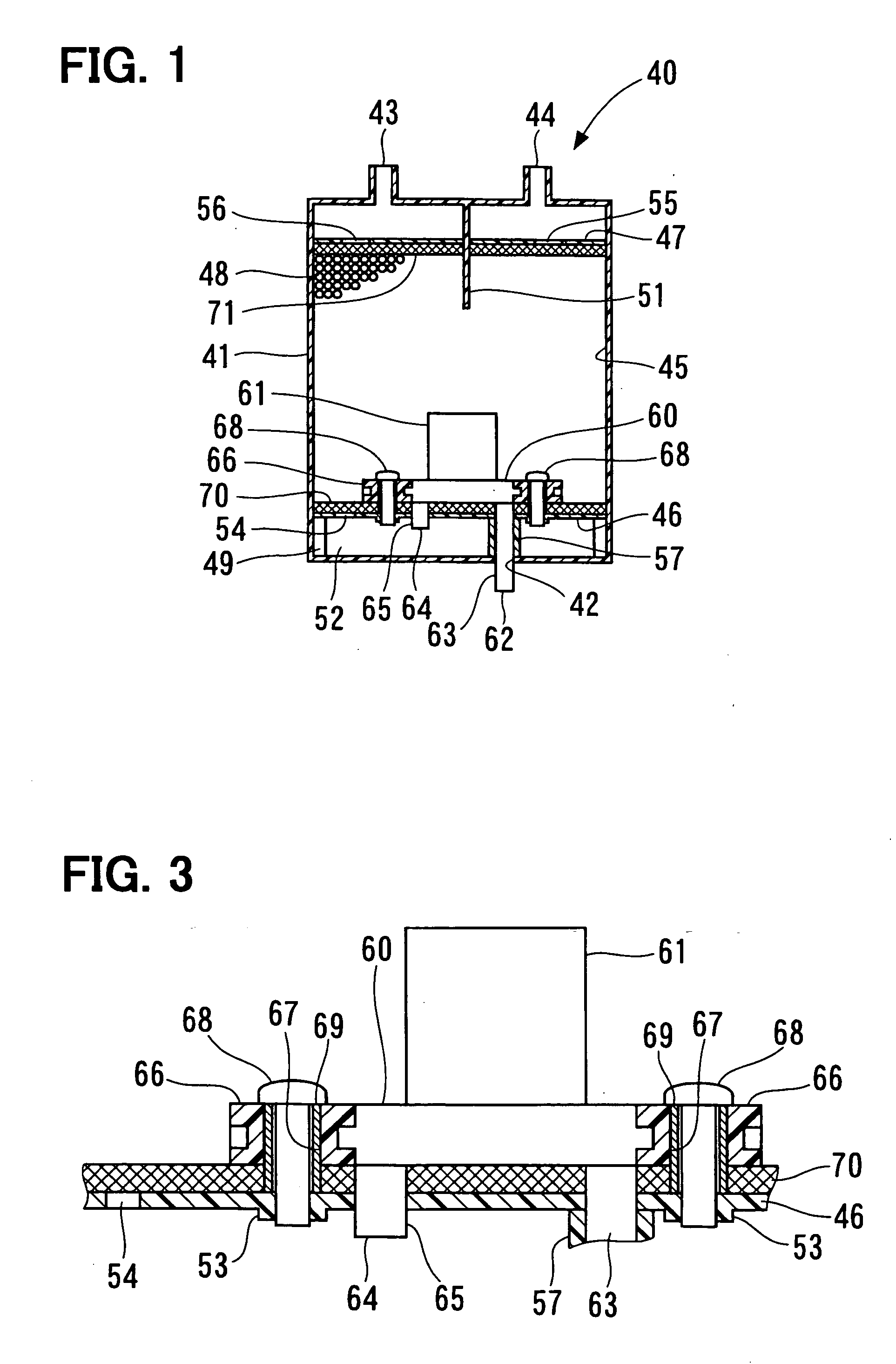
[0014] The first embodiment is described in reference to FIGS. 1 to 3. As shown in FIG. 2, a fuel vapor treatment apparatus 10 supplies fuel vapor in a fuel tank 12 of a vehicle into an intake pipe 16 of an engine 14. The fuel vapor treatment apparatus 10 includes a canister 40.
[0015] The intake pipe 16 of the engine 14 has an intake passage 18. The intake passage 18 is connected at one end thereof to an intake port 20 of the engine 14. An opposite end of the intake pipe 16 to the engine 14 connects to an air filter 22. The air filter 22 serves as an atmosphere introduction unit, which opens to the atmosphere to introduce atmospheric air into the intake passage 18, and removes foreign matters contained in atmospheric air as introduced. An atmospheric passage 24 and a purge passage 26 respectively branch from the intake passage 18. The atmospheric passage 24 branches from the downstream of the of the air filter 22 in the intake passage 18, and connects to the canister 40. The purge ...
second embodiment
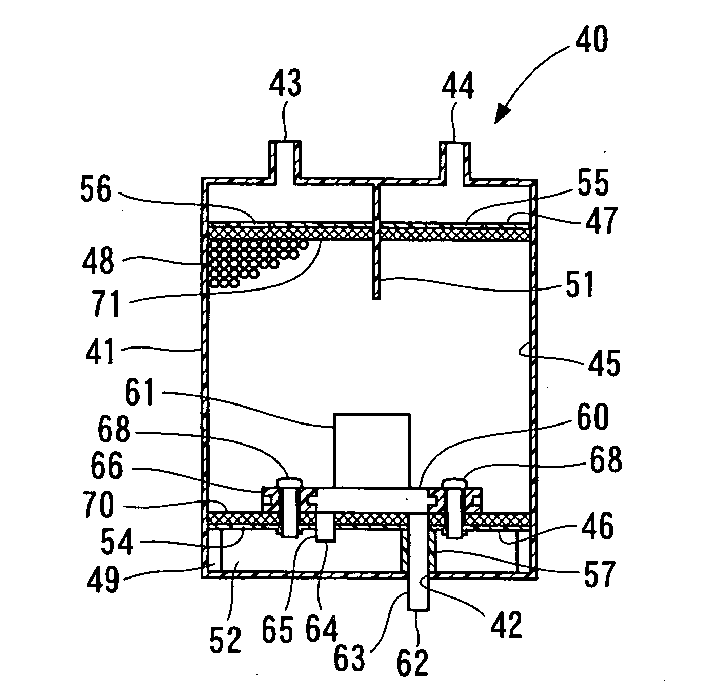
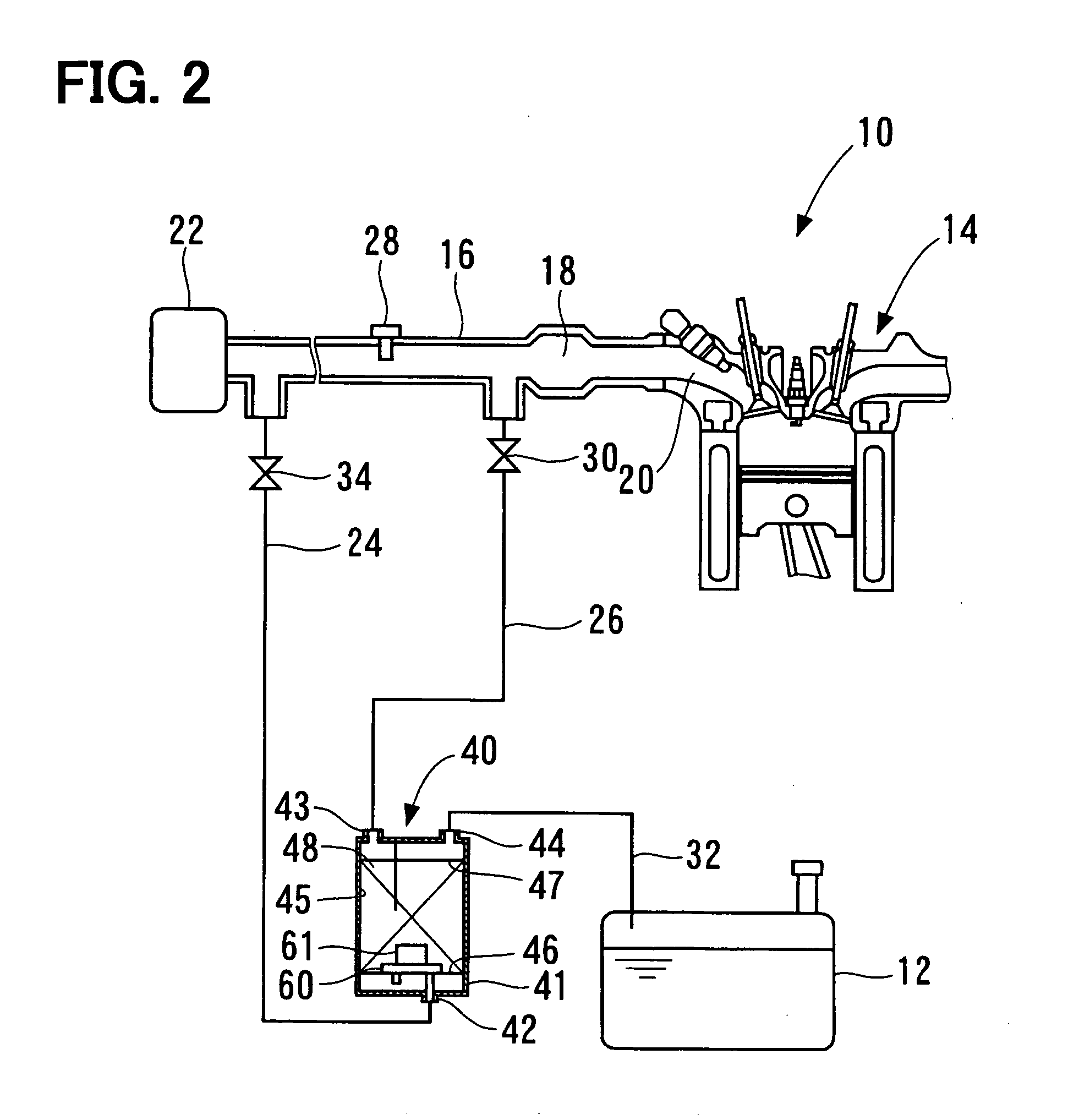
[0036] According to the second embodiment, as shown in FIG. 4, the pump 60 and the motor 61 are provided to the support plate 47. The inlet port 62 of the pump 60 connects to the interior of the accommodation chamber 45 charged with the adsorbent 48. The outlet port 64 of the pump 60 connects to the purge passage 26 (FIG. 2) through the purge port 43. In this structure, the pump 60 draws atmospheric air from the inlet port 62 connected to the accommodation chamber 45, and discharges the pressurized atmosphere into the purge passage 26, to which the outlet port 64 connects.
[0037] The pump 60 is provided to the support plate 47. More specifically, the pump 60 is supported by the casing 41 via the support plate 47. The pump 60 is fixed to the support plate 47 by the bolts 68 each extending through the ring 66 in the same manner as in the first embodiment. The filter 71 is interposed between the pump 60 and the support plate 47, such that the filter 71 covers the opening 55 formed in t...
third embodiment
[0041] According to the third embodiment, as shown in FIG. 5, the pump 60 and the motor 61 are provided inside the accommodation chamber 45, and are separated from the support plate 46. In this structure, the pump 60 and the motor 61 are substantially entirely covered with the adsorbent 48 charged in the accommodation chamber 45. The inlet pipe 63 and the outlet pipe 65 of the pump 60 are substantially entirely covered with the adsorbent 48 similarly to the pump 60 and the motor 61. The adsorbent 48 is solidly charged in the accommodation chamber 45. Therefore, the pump 60 and the motor 61 are supported by the casing 41 via the adsorbent 48 charged in the accommodation chamber 45.
[0042] According to the third embodiment, the adsorbent 48 is interposed between the pump 60 and the motor 61, and the casing 41. Therefore, sound and vibration caused from the pump 60 and the motor 61 are absorbed by the adsorbent 48. Thereby, sound and vibration transmitted to the casing 41 from the pump...
PUM
 Abstract
Description
Claims
Application Information