Structure for supporting energy conversion modules and solar energy collection system

a technology of solar energy collection and solar energy, applied in the direction of machine supports, heat collector mounting/support, light and heating apparatus, etc., can solve the problems of affecting the cost of the support structure used to mount the solar panels of the array in the proper position, hindering the widespread introduction of solar arrays for the generation of commercial and industrial electricity, and affecting the cost. , to achieve the effect of reducing the number of concrete supports and being stable in the wind

Inactive Publication Date: 2007-01-18
UNIRAC INC
View PDF25 Cites 23 Cited by
  • Summary
  • Abstract
  • Description
  • Claims
  • Application Information

AI Technical Summary

Benefits of technology

[0009] Accordingly, it is an advantage of the present invention that a structure for supporting energy conversion modules is provided.
[0010] It is another advantage of the present invention that a structure for supporting energy conversion modules is provided having a stable geometry that reduces the number of concrete footings.
[0011] Another advantage of the present invention is that a structure is provided for supporting energy conversion modules that is mechanically straightforward.
[0012] Yet another advantage of the present invention is that a structure is provided that is stable in wind and other weather phenomena.
[0013] The above and other advantages of the present invention are carried out in one form by a structure for supporting an array of energy conversion modules above a surface. The structure includes an elongated rigid member, a base coupled to a bottom edge of the rigid member for attachment to the surface, and posts extending from a top edge of the rigid member. The structure further includes torsion tubes, one each of the torsion tubes being pivotally retained by one each of the posts to form parallel rows of the torsion tubes. The torsion tubes are configured for attachment of the energy conversion modules to form the array.
[0014] The above and other advantages of the present invention are carried out in another form by a solar energy collection system. The system includes an array of flat, rectangular solar panels and a structure for supporting the solar panels above a surface. The structure includes an elongated rigid member, a base coupled to a bottom edge of the rigid member for attachment to the surface, and posts extending from a top edge of the rigid member. The structure further includes torsion tubes, one each of the torsion tubes being pivotally retained by one each of the posts to form parallel rows of torsion tubes. The torsion tubes are north-south oriented to define a north-south axis, and the solar panels are attached to the torsion tubes to form the array.

Problems solved by technology

Another a major cost element involved in the establishment of a wide-scale solar energy collection system is the cost of the support structure used to mount the solar panels of the array in proper position for receiving and converting solar energy.
Unfortunately, many of these support structures are so costly and mechanically complicated that they have hindered the widespread introduction of solar arrays for the generation of commercial and industrial electricity.
In addition to the mechanical complexity of such support structures, costs are also largely influenced by the number and size of the footings to which the support structure is fastened.
The cost of footings is governed by labor costs, soil conditions, and site preparation costs, as well as the cost and availability of concrete.
A shortage of cement, the basic ingredient for concrete, has been exacerbated by a continued housing boom and import constraints, and has resulted in significant increases in the cost of cement.
The shortage of cement afflicts many regions, and is particularly problematic in the United States across the sunbelt, from Florida to California.
As a result of the cost and mechanical complexity of existing solar energy collection systems, and the costs associated with constructing the footings to which the support structure is fastened, there has been an unwillingness to proceed with wide-scale solar energy collection systems, despite their obvious advantages in terms of desired environmental effects and conservation of fossil energy sources.

Method used


Image

  • Structure for supporting energy conversion modules and solar energy collection system
  • Structure for supporting energy conversion modules and solar energy collection system
  • Structure for supporting energy conversion modules and solar energy collection system

Examples


Embodiment Construction

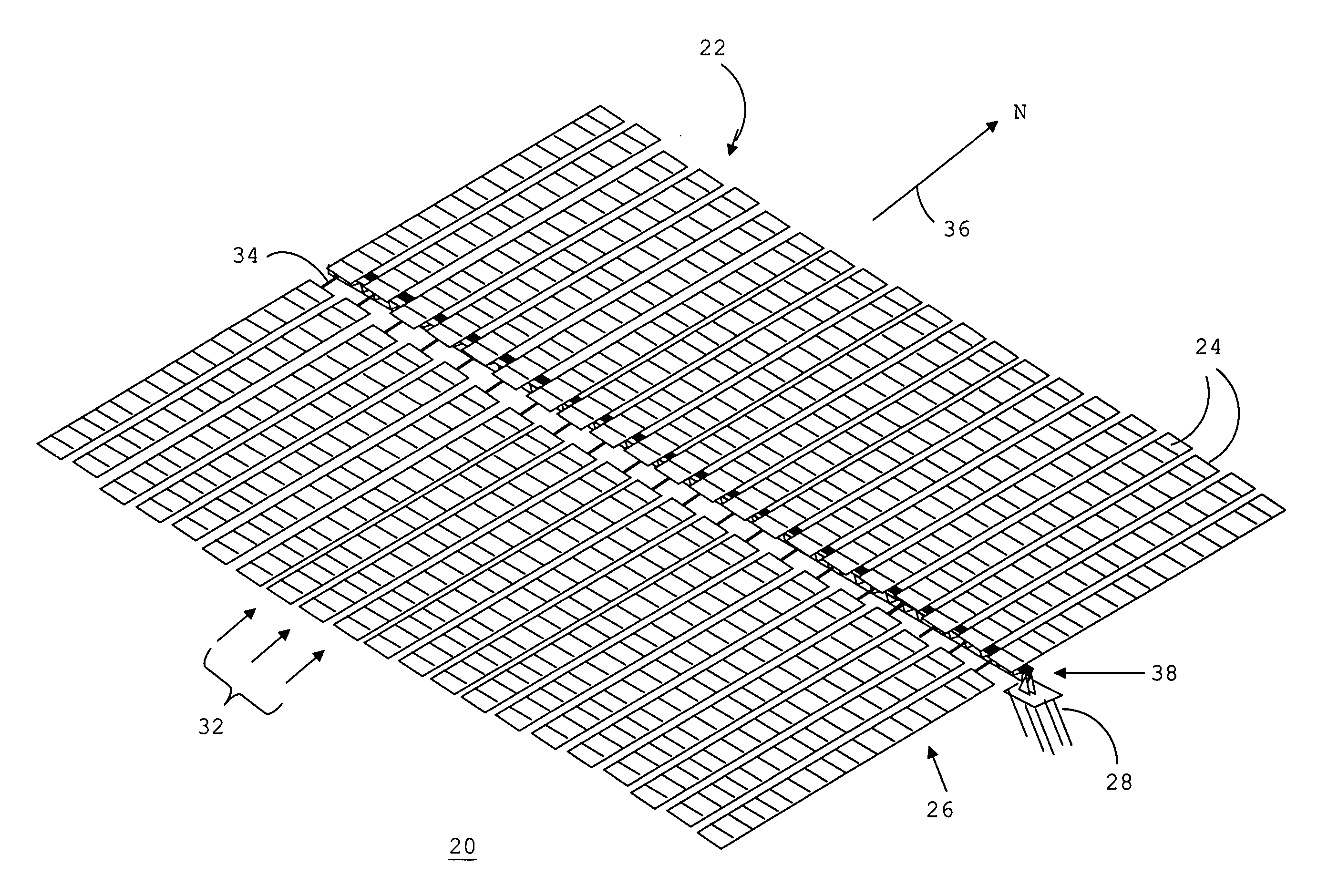
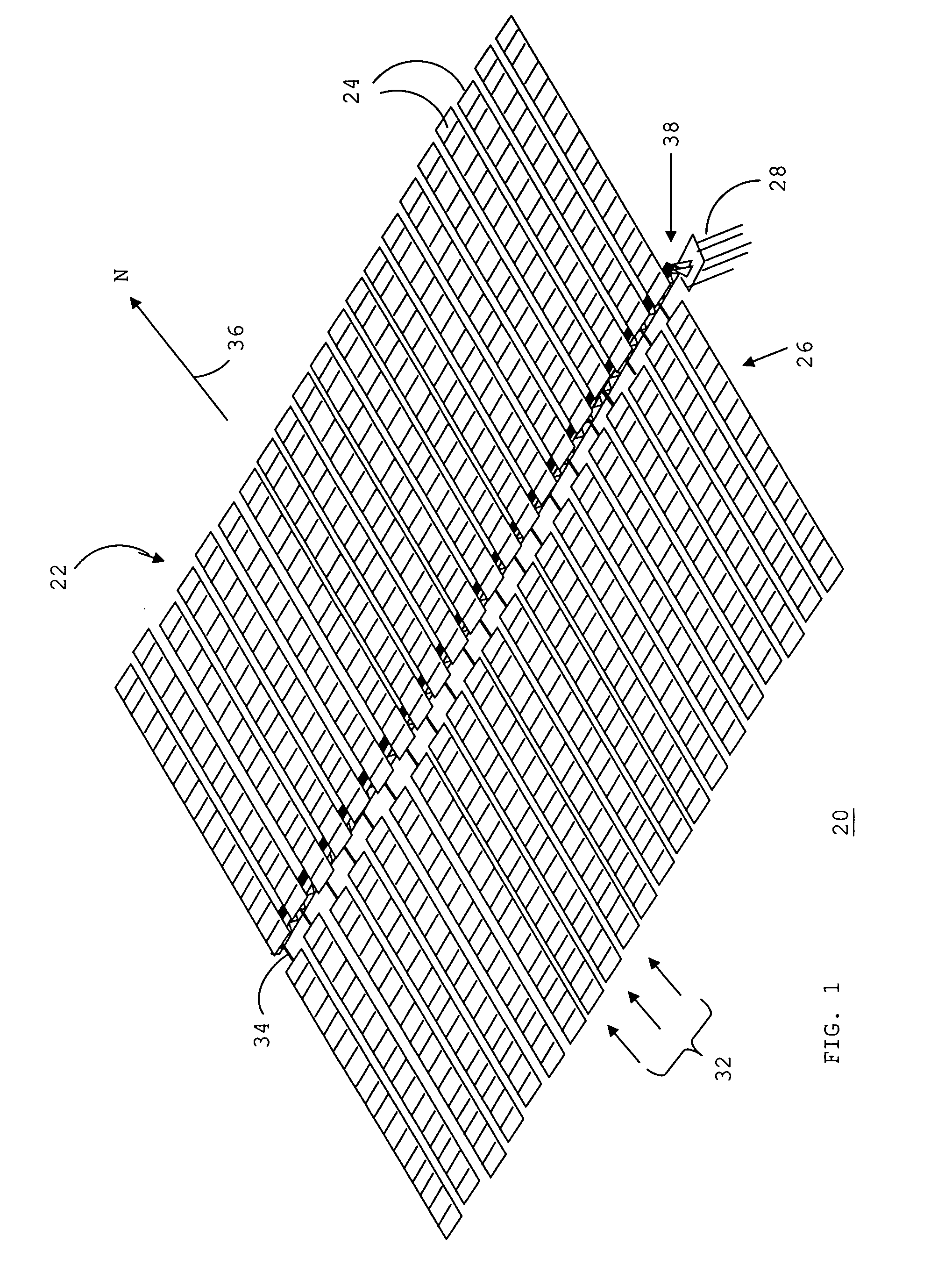
[0028]FIG. 1 shows a perspective view of a solar energy collection system 20 for collecting solar energy in accordance with a preferred embodiment of the present invention. Solar energy collection system 20 is a single-axis solar tracking system. A single-axis tracking system represents a reasonable compromise between fixed, non-tracking, systems and multiple-axis tracking systems. That is, a single-axis tracking system achieves the benefit of an increase in efficiency over a fixed system without the undesirable complexity and cost of a multiple-axis tracking system.

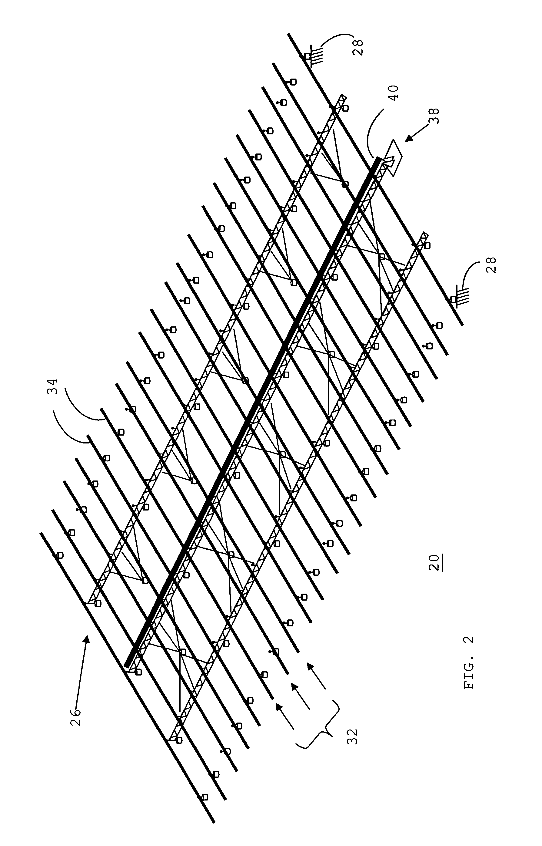
[0029] System 20 generally includes an array 22 of flat, rectangular energy conversion modules 24 and an underlying support structure 26 for supporting array 22 above a surface 28 of the earth. System 20 moves array 22 of energy conversion modules 24 around a single axis, and therefore approximates tracking of the actual position of the sun.

[0030] Each of energy conversion modules 24 incorporates at least one device, e...


PUM


Abstract

A structure (26) for supporting an array (22) of solar panels (24) in a solar energy collection system (20) includes a support assembly (42) formed from a rigid subassembly (44). The subassembly (44) includes an elongated truss (68), a base (46) coupled to the truss (68) for attachment to a footing (48), and posts (50) extending from a top edge of the truss (68). The structure (26) further includes torsion tubes (34), each of which is pivotally retained by one of the posts (50) to form parallel rows (32) of torsion tubes (34). A number of rigid subassemblies (44) can be interconnected to further increase the number of rows (32) of the system (20). The solar panels (24) are attached to the torsion tubes (34) to form the array (22), and a drive mechanism (38) pivots the torsion tubes (34) via a single elongated actuator and multiple torque arms (90).

Description

TECHNICAL FIELD OF THE INVENTION [0001] The present invention relates to the field of solar energy collection systems. More specifically, the present invention relates to a structure for supporting an array of solar energy conversion modules. BACKGROUND OF THE INVENTION [0002] Due to the finite supply of fossil energy sources, the global environmental damage caused by fossil fuels, increasing energy demand, and economic forces, society is becoming compelled to diversify energy resources. One such technology that has received significant attention is the use of solar energy. [0003] Solar energy collection systems are used for a variety of purposes, for example, as utility interactive power systems, power supplies for remote or unmanned sites, and cellular phone switch-site power supplies. An array of energy conversion modules, such as, photovoltaic (PV) modules, in a solar energy collection system can have a capacity from a few kilowatts to a hundred kilowatts or more, depending upon...

Claims


Application Information

Patent Timeline
Patent Type & Authority Applications(United States)
IPC IPC(8): F24J2/38F24S50/20F24S23/77
CPCF24J2/525F24J2/541Y02E10/47F24J2002/5468F24J2002/5486F24J2002/5286F24S25/617F24S30/425F24S2025/017F24S2030/136F24S2030/16Y02E10/50A45D19/04H02S20/00
Inventor HAYDEN, HERBERT T.
Owner UNIRAC INC
Why Eureka
Try Eureka