Heat Transfer Device

a heat transfer device and heat transfer technology, applied in indirect heat exchangers, semiconductor/solid-state device details, lighting and heating apparatus, etc., can solve the problems of generating heat as a major obstacle to improving the performance of electronic devices and systems, solid diffusion can only marginally satisfy the cooling requirement, and its construction can be too expensive for adaptation in commodity markets such as the desktop pc mark

Inactive Publication Date: 2007-01-18
CONVERGENCE TECH LTD
View PDF0 Cites 55 Cited by
  • Summary
  • Abstract
  • Description
  • Claims
  • Application Information

AI Technical Summary

Benefits of technology

[0007] A heat transfer device includes a vapor chamber that houses a phase change material such as water. The heat transfer device may be selectively formed from a combination of polymeric and non-polymeric materials. In one embodiment, the vapor chamber is formed from a polymer layer surrounding a sealing layer formed from non-polymeric material. The heat transfer device may further include one or more fin members operable to diffuse heat from the vapor chamber to the ambient/outside environment. The fins may be solid structures, or may each define a fin chamber in communication with the vapor cham

Problems solved by technology

As electronic components and devices decrease in size while increasing in operational speed, generated heat becomes a major obstacle to improving performance in electronic devices and systems.
With the demand of the high cooling requirement, solid diffusion can only marginally satisfy the cooling requirement.
Although the vapor chamber can be utilize

Method used


Image

  • Heat Transfer Device
  • Heat Transfer Device
  • Heat Transfer Device

Examples


Embodiment Construction

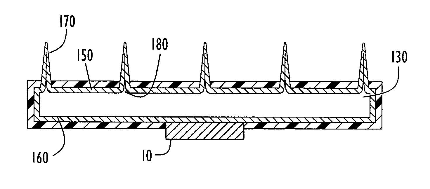
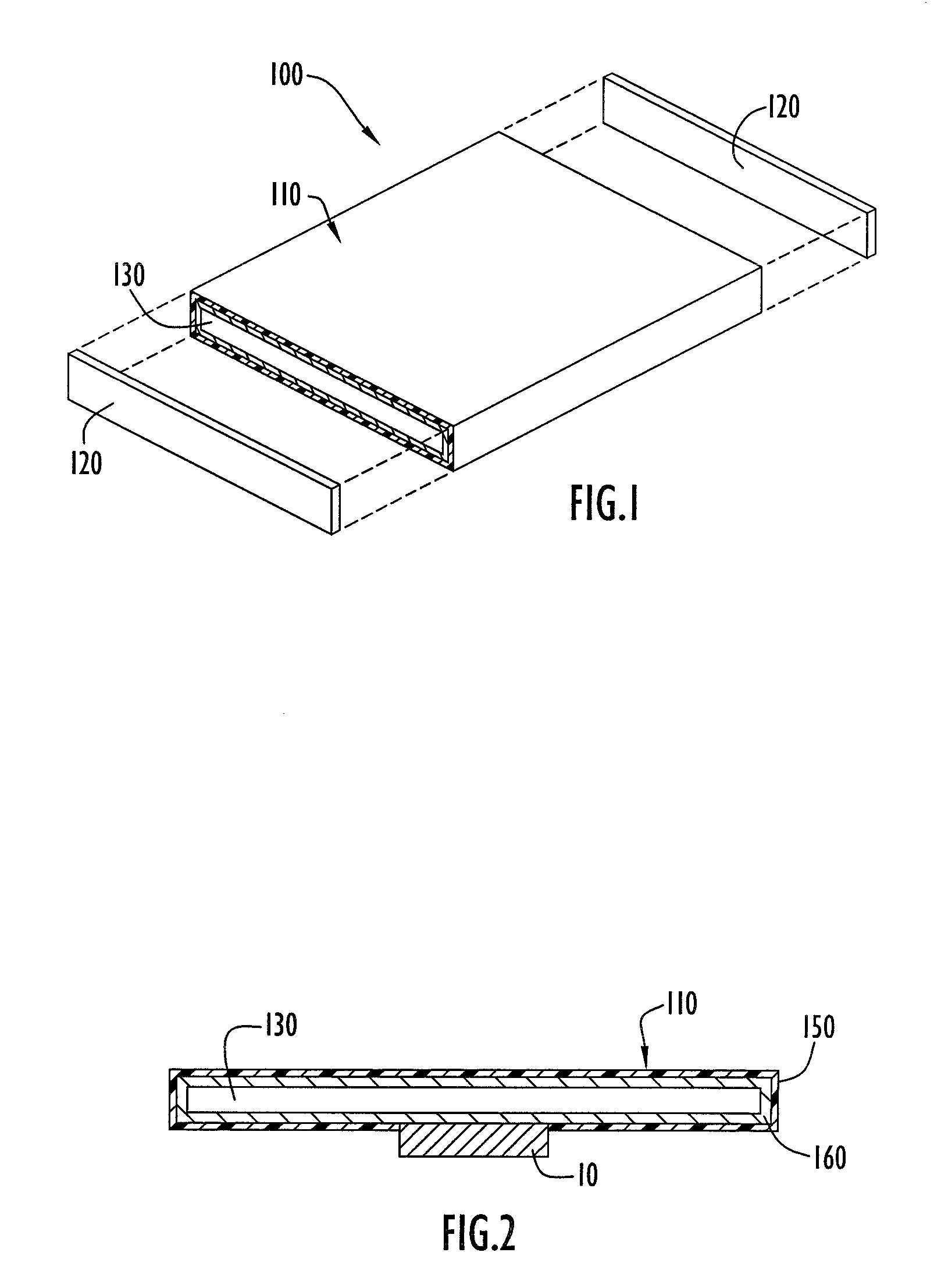
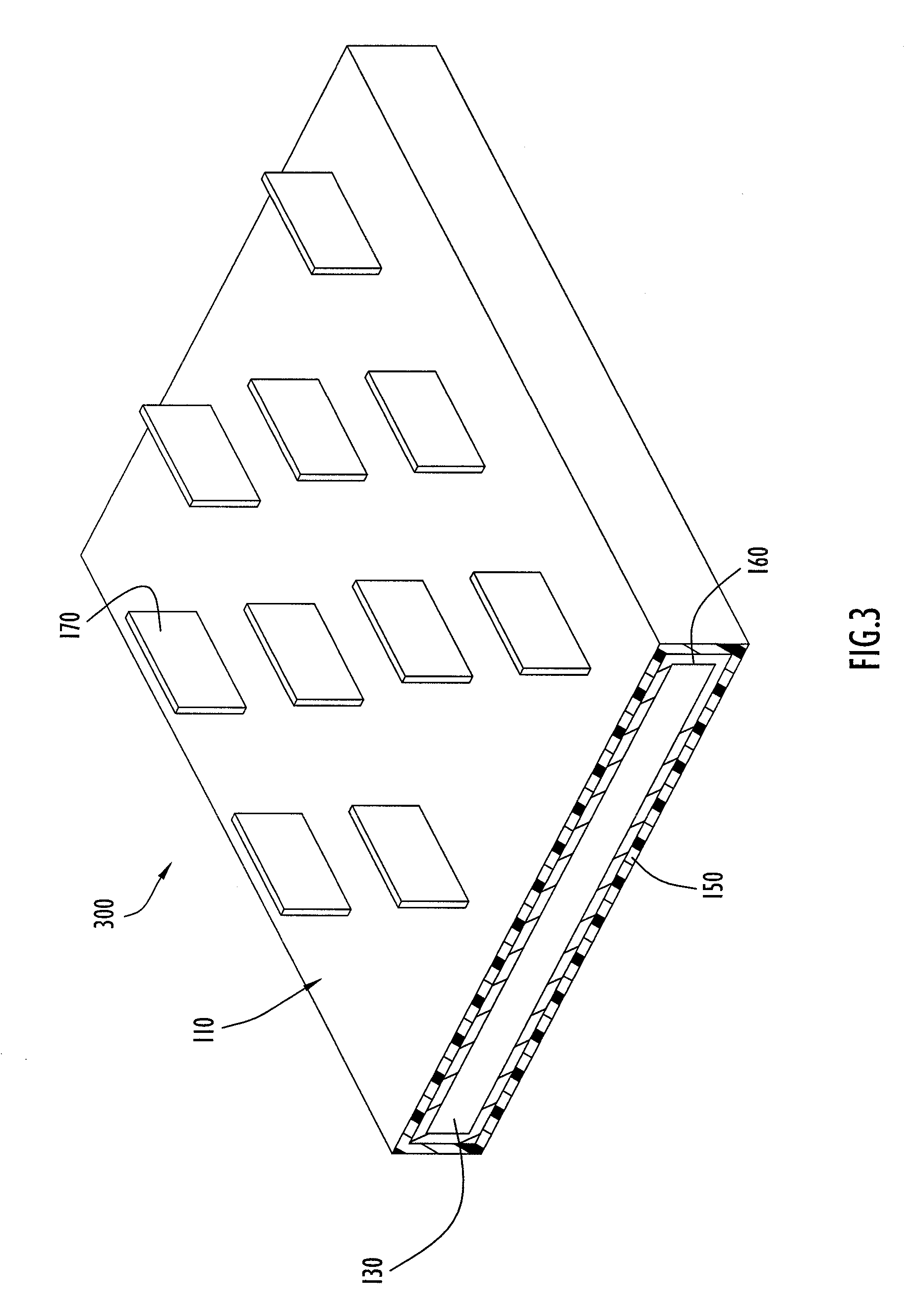
[0020]FIG. 1 is a heat transfer device 100 according to an embodiment of the invention. As shown, the heat transfer device 100 may be a heat sink formed from a folded plate chamber including a generally hollow body 110 and two end caps 120. The body 110 defines a vapor chamber 130, i.e., an enclosure under vacuum pressure. The vapor chamber 130 may house at least one type of phase change material. This material can be solid, liquid, or gaseous, and can be a mixture or pure substance. By way of example, the phase change material may be a refrigerant, water, alcohol, ammonia, etc. In operation, the heat transfer device 100 absorbs heat form a heat source 10 (FIG. 2) such as an electronic device. The heat from the heat source 10 causes the liquid phase change material to evaporate, generating vapor that is transported to the interior surface of the device 100. When the vapor leaves the evaporation zone (i.e., the area in the immediate vicinity of the heat source), the vapor condenses, ...


PUM

PropertyMeasurementUnit
Flow rateaaaaaaaaaa
Adhesion strengthaaaaaaaaaa
Heataaaaaaaaaa

Abstract

A heat transfer device includes a vapor chamber that houses a phase change material such as water. The heat transfer device may be selectively formed from a combination of polymeric and non-polymeric materials. In one embodiment, the vapor chamber is formed from a polymer layer surrounding a sealing layer formed from non-polymeric material. The heat transfer device may further include one or more fin members operable to diffuse heat from the vapor chamber to the ambient/outside environment. The fins may be solid structures, or may each define a fin chamber in communication with the vapor chamber. In one embodiment, the fin members are formed from non-polymeric material.

Description

CROSS-REFERENCE TO RELATED APPLICATION [0001] This application claims priority from U.S. Provisional Patent Application Ser. No. 60 / 693,484, entitled “Organic-Inorganic Vapor-Augmented Heatsink” and filed 24 Jun. 2005. The disclosure of the above-mentioned provisional application is incorporated herein by reference in its entirety.TECHNICAL FIELD [0002] This invention relates to heat transfer devices, and more particularly, to a vapor augmented heat sink device selectively formed from both polymeric and non-polymeric materials. BACKGROUND OF THE INVENTION [0003] As electronic components and devices decrease in size while increasing in operational speed, generated heat becomes a major obstacle to improving performance in electronic devices and systems. The development of high performance heat transfer devices becomes a major focus of the industry. [0004] A heat transfer device is often used for removing the heat from a system to the ambient environment. In particular, a heat sink (an...

Claims


Application Information

Patent Timeline
IPC IPC(8): H05K7/20
CPCF28D15/0233F28D15/046F28F1/14F28F1/16F28F21/062H01L23/427H01L2924/0002H01L2924/3011F28F2215/06F28F19/06H01L2924/00F28D15/02
Inventor SIU, WING MING
Owner CONVERGENCE TECH LTD
Why Eureka
Try Eureka