

Miniature aircraft
a technology for miniature aircraft and wings, applied in the field of miniature aircraft, can solve the problems of difficult placement of cables and winding of cables around the axles
- Summary
- Abstract
- Description
- Claims
- Application Information
AI Technical Summary
Benefits of technology
Problems solved by technology
Method used
Image

Examples
first embodiment
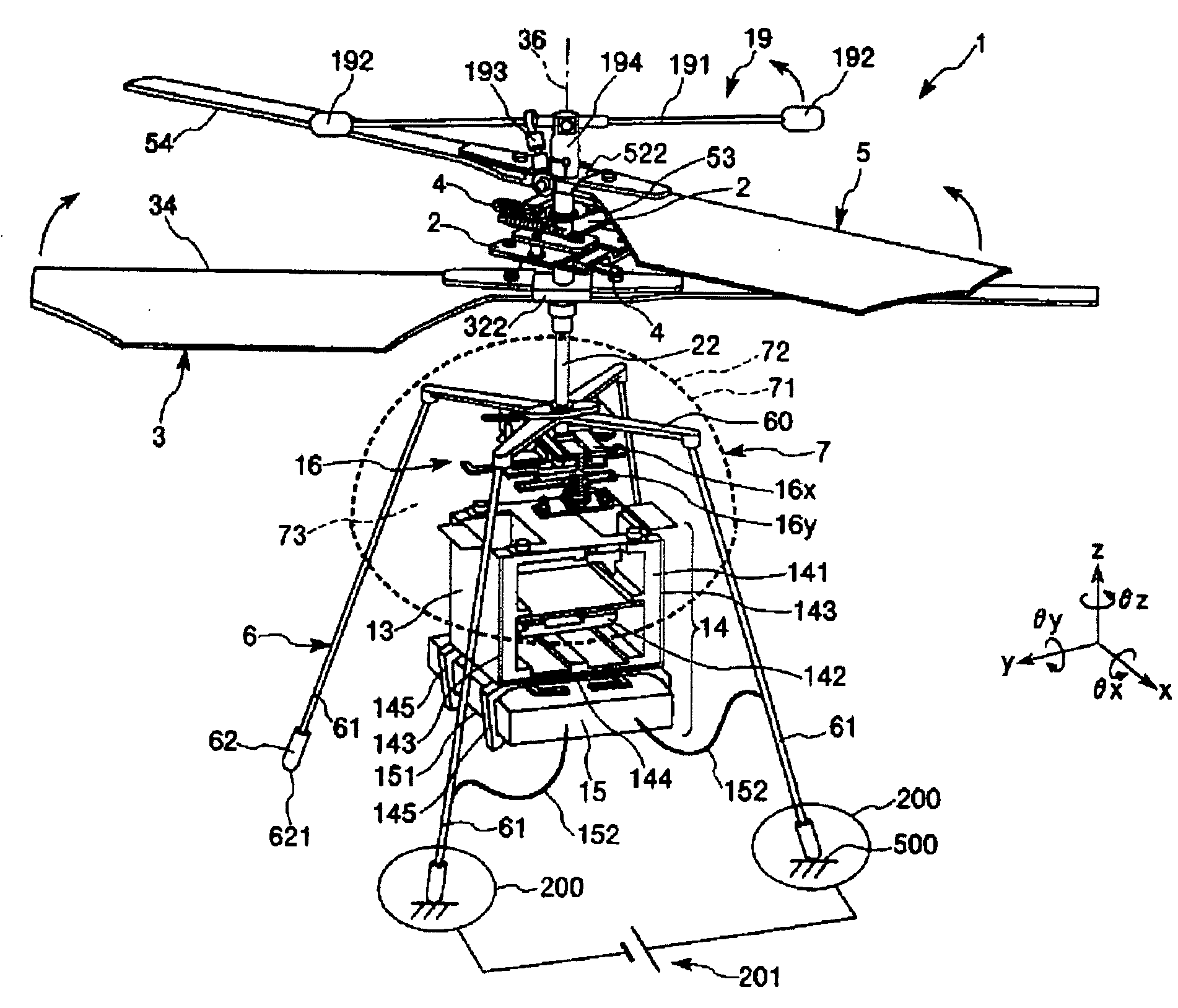
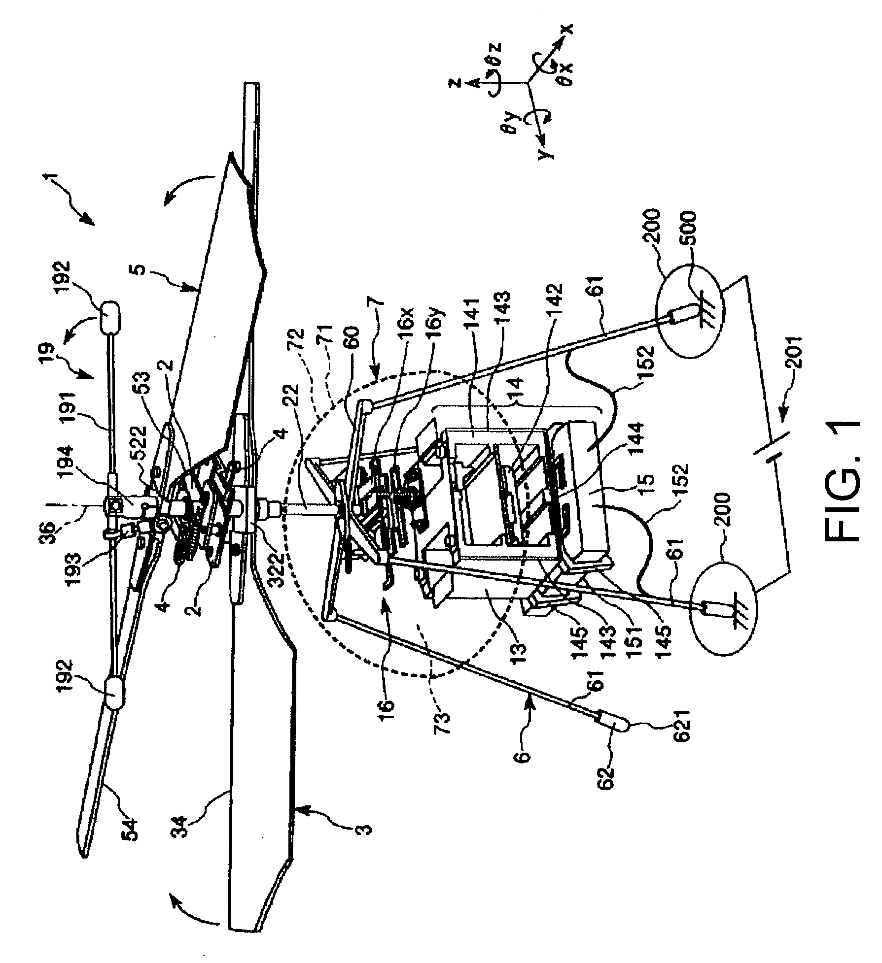
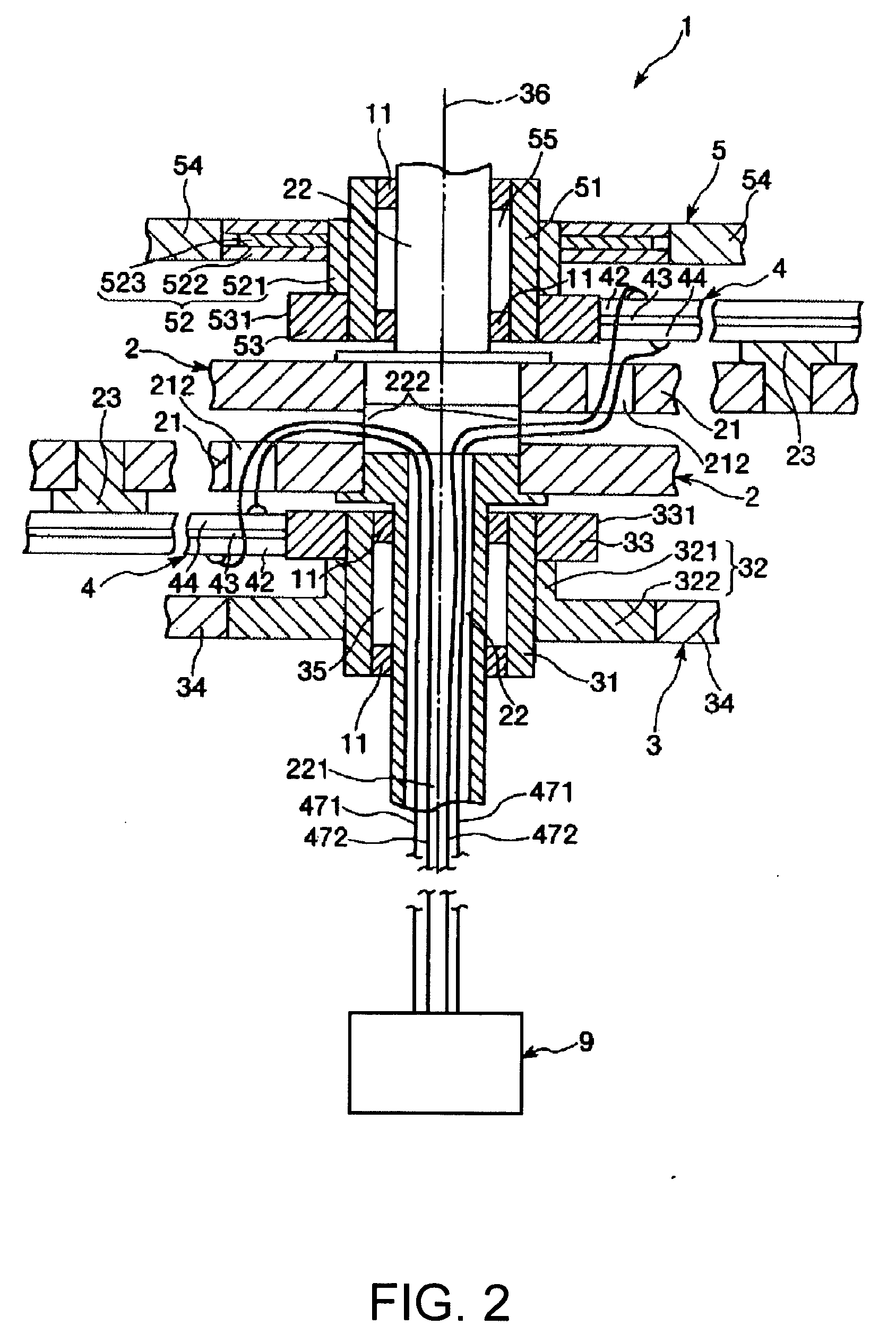
[0078]FIG. 1 is a perspective view showing the first embodiment of the miniature aircraft of the present invention, FIG. 2 is a cross-sectional side view showing an enlargement of the area near the center axle in the miniature aircraft shown in FIG. 1, FIG. 3 is a perspective view showing a stabilizer bar and the surrounding area in the miniature aircraft shown in FIG. 1, FIG. 4 is a perspective view of a vibrating member in the miniature aircraft shown in FIG. 1, FIG. 5 is a plan view showing the manner in which the vibrating member drives a driven member in the miniature aircraft shown in FIG. 1, FIG. 6 is a plan view showing the manner in which the convexity of the vibrating member moves in an elliptical pattern in the miniature aircraft shown in FIG. 1, FIG. 7 is a perspective view of the orientation varying device (orientation changer) in the miniature aircraft shown in FIG. 1, FIG. 8 is a perspective view of a linear actuator of the orientation varying device in the miniature ...
second embodiment
[0302]FIG. 24 is a cross-sectional view showing the second embodiment of the miniature aircraft of the present invention.
[0303] Hereinbelow, the second embodiment of the miniature aircraft of the present invention is described with reference to the diagrams. The description focuses on the differences with the embodiment previously described, and descriptions of similar aspects are omitted.
[0304] The present embodiment is similar to the first embodiment except that the configuration of the energy storage device is different.
[0305] In the miniature aircraft 1A, the energy storage device is configured from a fuel cell 30.
[0306] As shown in FIG. 24, the fuel cell 30 has a fuel tank 301, a Seebeck element 302 (for example, see Japanese Laid-Open Patent Application No. 2004-140048), and a heat generating unit 303.
[0307] The fuel tank 301 is a unit for accommodating (storing) butane or another such fuel, for example. The fuel tank 301 is placed (fixed) on the underside of the fixed pa...
third embodiment
[0316]FIG. 25 is a perspective view showing the third embodiment of the miniature aircraft of the present invention, and FIG. 26 is a front view depicting a condition in which the miniature aircraft shown in FIG. 25 is grounded.
[0317] Hereinbelow, the third embodiment of the miniature aircraft of the present invention is described with reference to the diagrams. The description focuses on the differences with the embodiments previously described, and descriptions of similar aspects are omitted.
[0318] The present embodiment is similar to the first embodiment except that the shape of the fixed part of the grounding device is different.
[0319] As shown in FIG. 25, the fixed part 60B of the miniature aircraft 1B is configured from a plate in the shape of a square.
[0320] U-shaped grooves 631, 632, 633, and 634 that run through the fixed part 60B in the thickness direction (z-axis direction) are provided to (formed in) the fixed part 60B.
[0321] The groove 631 and groove 632 are dispos...
PUM
 Abstract
Description
Claims
Application Information