Transverse flux electrical machine with segmented core stator

a technology of electrical machines and stators, applied in the direction of synchronous machines with stationary armatures and rotating magnets, magnetic circuit shapes/forms/construction, electrical apparatus, etc., can solve the problems of non-machined stators, increased inaccuracy of air gap thickness, and inability to machine stators

Inactive Publication Date: 2007-01-18
EOCYCLE TECH
View PDF13 Cites 47 Cited by
  • Summary
  • Abstract
  • Description
  • Claims
  • Application Information

AI Technical Summary

Benefits of technology

[0012] Another aspect of the invention provides a method for manufacturing a component for a transverse flux electrical machine, comprising: fixing a plurality of U-shaped magnetic cores around a rotation axis such that the open side of the U-shaped magnetic cores points in a radial direction; winding an electrical conductor coil such that the coil rests in the interior area of all of the U-shap...

Problems solved by technology

In this case, it is not possible to machine the stator to ensure its circle symmetry, without short-circuiting the metal sheets with one another.
A non-machined stator increases the inaccuracy of the thickness of the air gap between the stator and the rotor.
Also, in the case where the horseshoe shaped soft iron cores are made of identical piled up metal sheets, additional magne...

Method used


Image

  • Transverse flux electrical machine with segmented core stator
  • Transverse flux electrical machine with segmented core stator
  • Transverse flux electrical machine with segmented core stator

Examples


Embodiment Construction

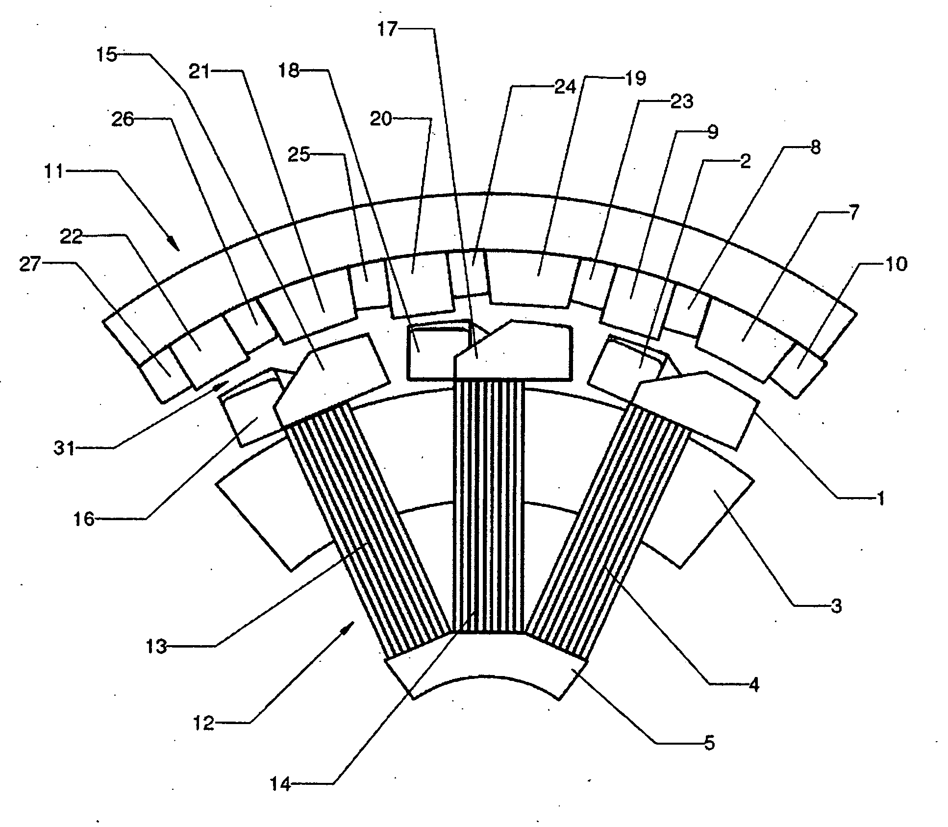
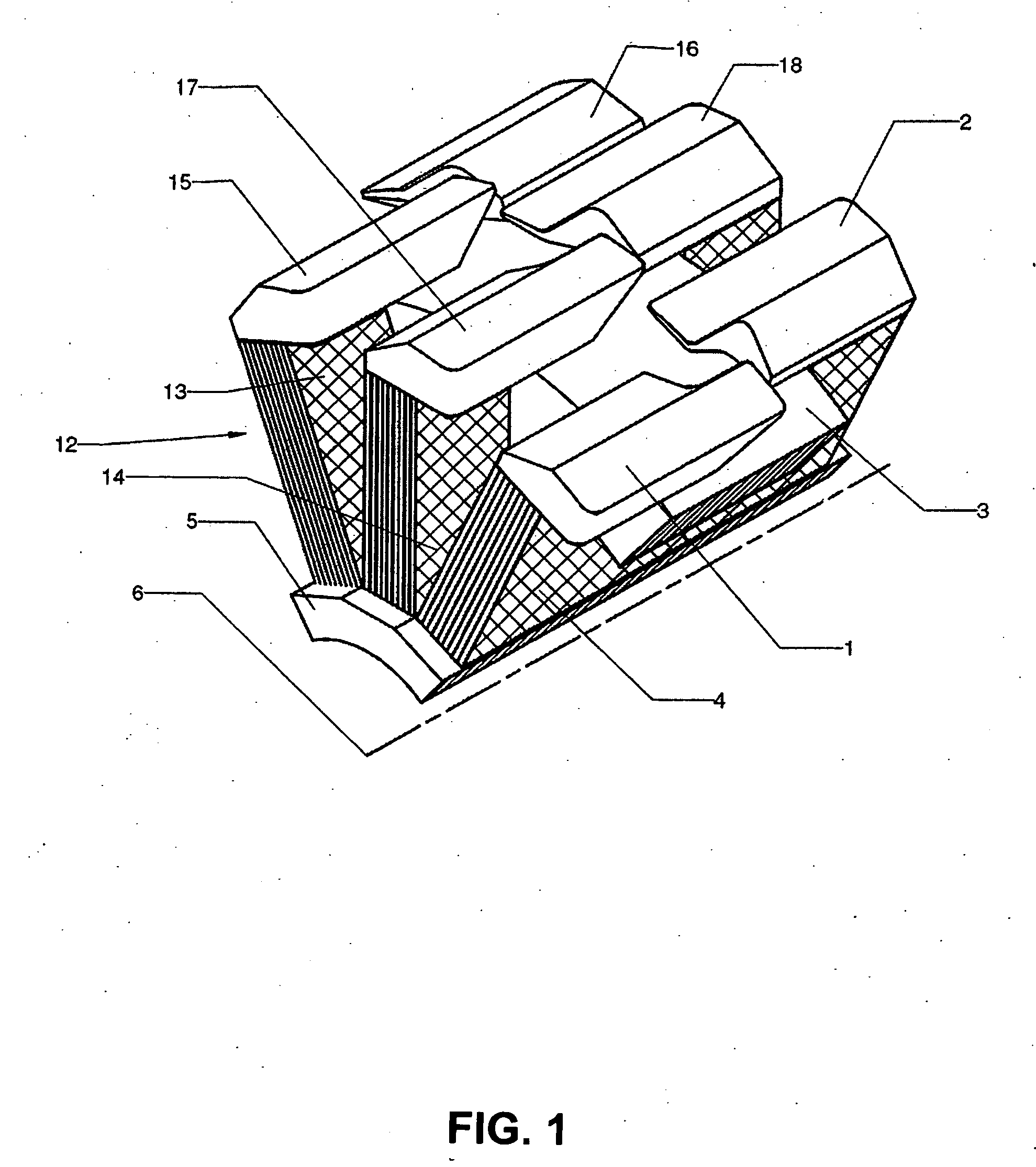
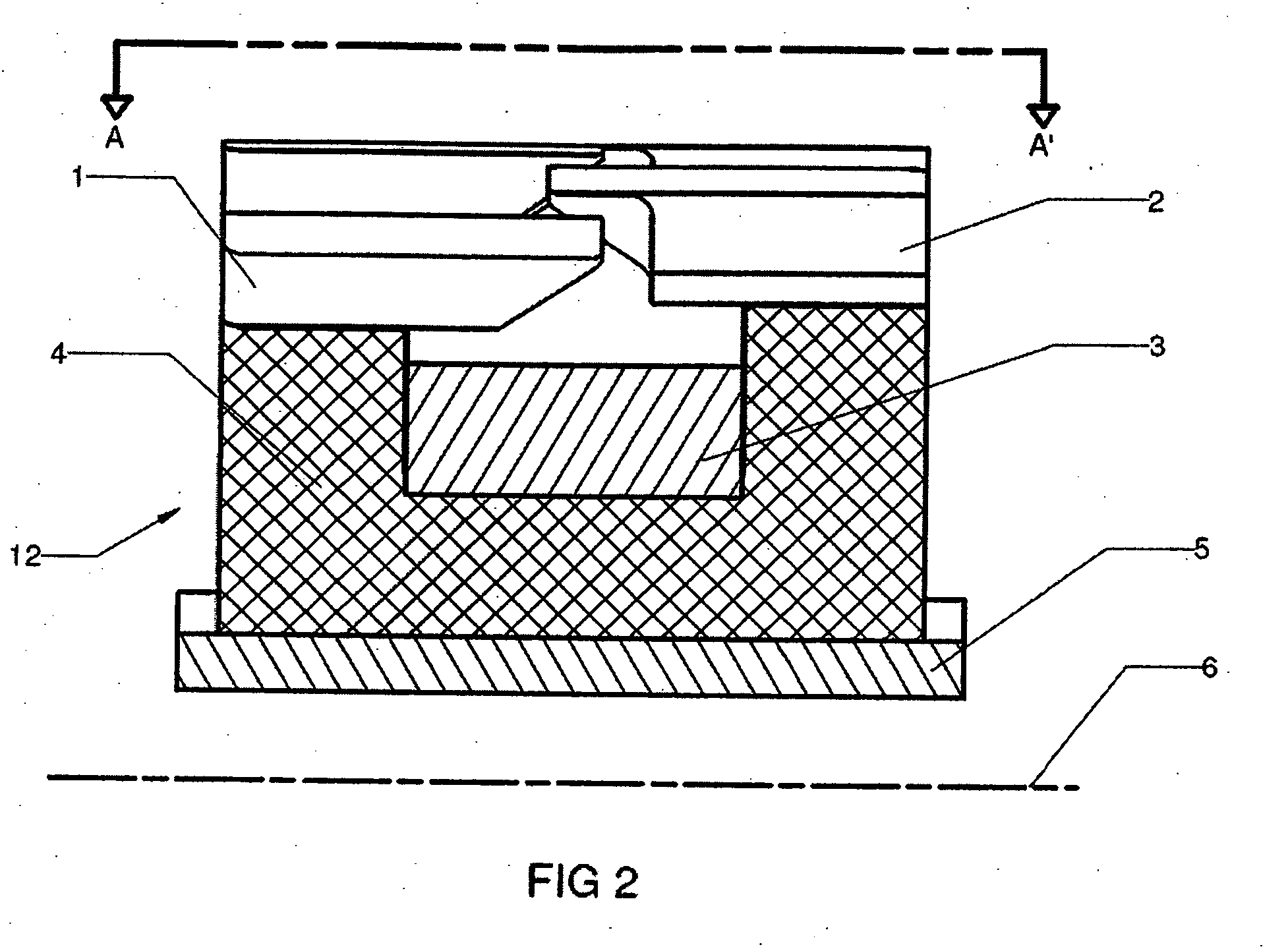
[0024] In FIGS. 1, 3 and 4 part of stator 12 of a single-phase transverse flux machine according to an embodiment of the invention is illustrated, the rotor not being represented. In this embodiment, the transverse flux machine includes a number of magnetic poles 2p, FIGS. 1, 3 and 4 illustrating 6 magnetic poles only among the 2p magnetic poles which are included in a phase of the machine. Three of a number of p magnetic cores are illustrated. Each magnetic core comprises a U-shaped soft iron stator core 4, 13, 14 and two identical magnetic feet 1, 2, 15, 16, 17, 18. The U-shaped soft iron stator cores 4, 13, 14, rest on the holding cylinder of the stator 5 and are held in place by means of the coil of electrical conductors 3 disposed inside the U-shaped soft iron stator cores 4, 13, 14 so that it is wound around the p U-shaped soft iron stator cores. The holding cylinder of the stator is of generally cylindrical shape and is centered on the axis of rotation 6 of the machine. The m...


PUM


Abstract

The invention relates to a transverse flux electrical machine, comprising a rotor and a stator. The rotor has magnets, angularly adjacent magnets having magnetic polarizations of opposite directions. The stator has a plurality of magnetic cores annularly disposed along the stator. Each core comprises a U-shaped part and a magnetic foot. The U-shaped part is disposed such that its open side faces the air gap between the rotor and the stator and that a segment of a magnetic flux circulating in the U-shaped part is substantially parallel to the rotation axis. The magnetic foot is assembled to the U-shaped part such that it is contiguous to the air gap. The magnetic foot provides a magnetic pole. An electrical conductor coil is disposed in the interior area of all of the U-shaped parts.

Description

CROSS-REFERENCE TO RELATED APPLICATIONS [0001] This application claims priority under 35USC§119(e) of U.S. provisional patent application No. 60 / 694,695 filed on Jun. 29, 2005 in the French language by Applicant. Translations of this application in the English language have been made of record. This application and its translation in the English language are incorporated herein by reference.BACKGROUND OF THE INVENTION [0002] 1) Field of the Invention [0003] This invention relates to a transverse flux electrical machine, that can be used as an alternator or a motor, and that is intended to be used for the conversion of a rotary movement into electrical power, and vice versa. [0004] 2) Description of the Prior Art [0005] Transverse flux electrical machines include a circular stator and a circular rotor, which are separated by an air space called an air gap, that allows free rotation of the rotor with respect to the stator, and wherein the stator comprises soft iron cores, that direct ...

Claims


Application Information

Patent Timeline
IPC IPC(8): H02K21/12H02K1/12
CPCH02K1/145H02K1/243H02K2201/12H02K21/16H02K21/227H02K21/12
Inventor DUBOIS, MAXIME R.POLINDER, HENK
Owner EOCYCLE TECH
Why Eureka
Try Eureka