Image processor, image processing method, recording medium, computer program and semiconductor device

a technology of image processing and image processor, which is applied in the field of image processing technology, can solve the problems of not being able to use images taken so far for a purpose, prone to input errors, and troublesome and time-consuming to enter desired commands using the keyboard

Inactive Publication Date: 2007-01-18
SONY COMPUTER ENTERTAINMENT INC
View PDF11 Cites 134 Cited by
  • Summary
  • Abstract
  • Description
  • Claims
  • Application Information

AI Technical Summary

Problems solved by technology

For example, for a person who never touched the keyboard before, entering desired commands using the keyboard is quite troublesome and time-consuming, and prone to input errors due to mistyping from the keyboard.
However, images taken have not been used so far for a purpose such as entering commands to a computer, for example.

Method used


Image

  • Image processor, image processing method, recording medium, computer program and semiconductor device
  • Image processor, image processing method, recording medium, computer program and semiconductor device
  • Image processor, image processing method, recording medium, computer program and semiconductor device

Examples


embodiment 1

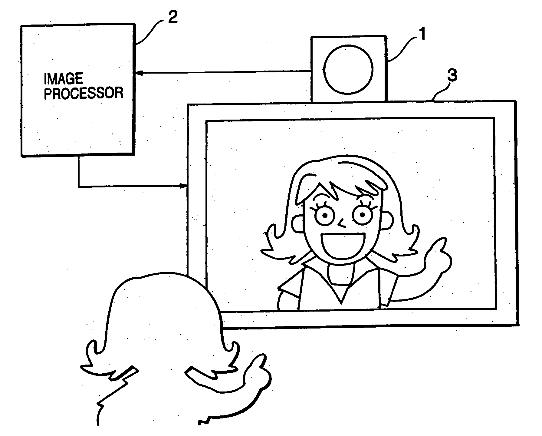
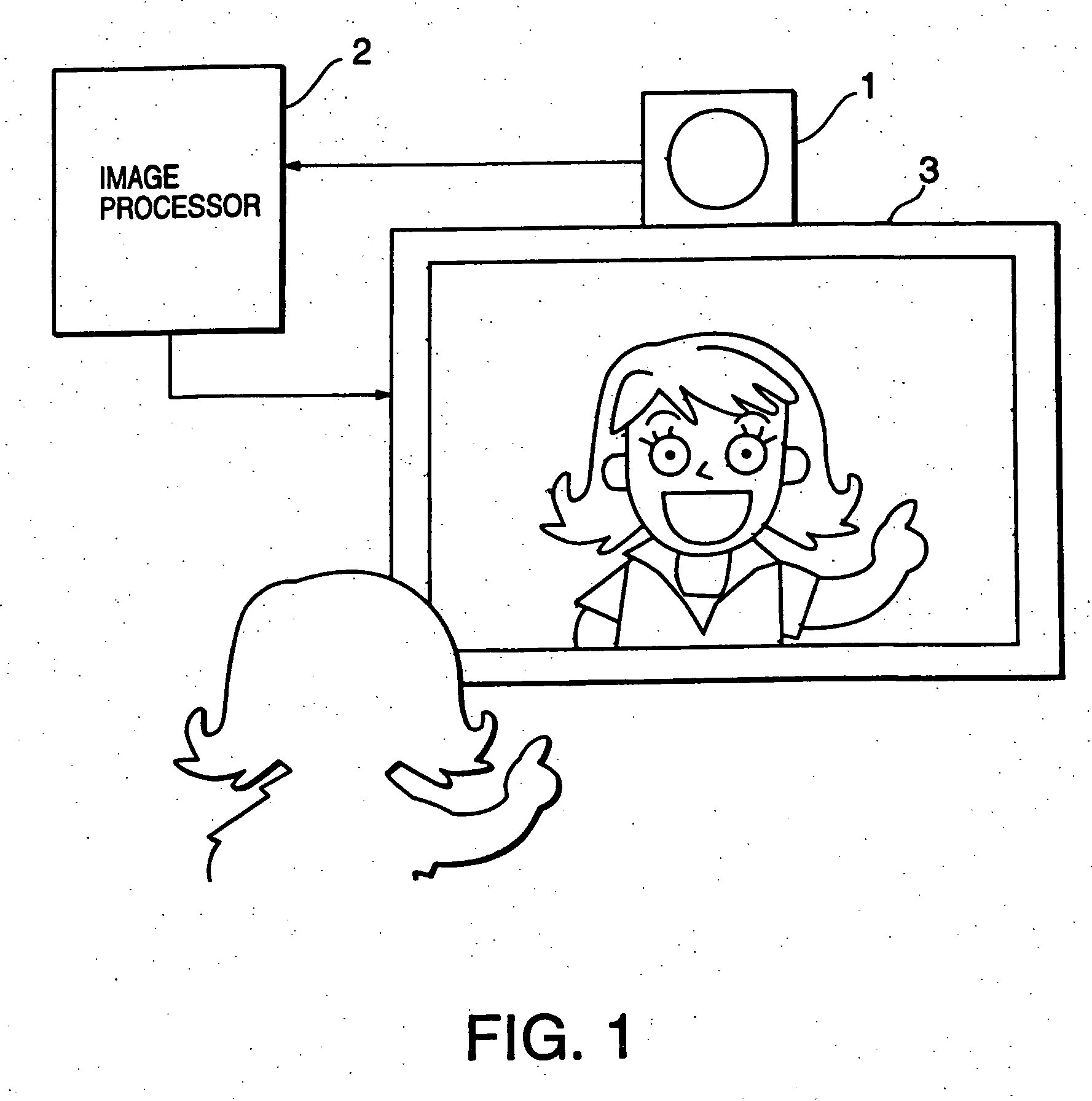
[0086] On the display device 3, as shown in FIG. 6, suppose the image processor 2 displays a combined image consisting of the mirrored moving image of the operator taken by the video camera 1 and subjected to mirroring with a menu image as an example of an object image superimposed.

[0087] As a target, it is possible to select various objects such as the eyes, mouth, hands, etc. of the operator. Here, a case will be described where the operator's hand is the target and instructions are entered to the menu image by detecting the amount of movement of the hand in the area in which the menu image is displayed.

[0088] The menu image has a hierarchic structure as shown in FIG. 7. When the operator selects “menu” at the top layer, a pull-down image highlighting one of “select1”, “select2” or “select3” at the lower layer is displayed and when one item is selected from the pull-down image, the process determining image (for example, “process 21”, “process 22”, “process 23”, “process 24”) of...

embodiment 2

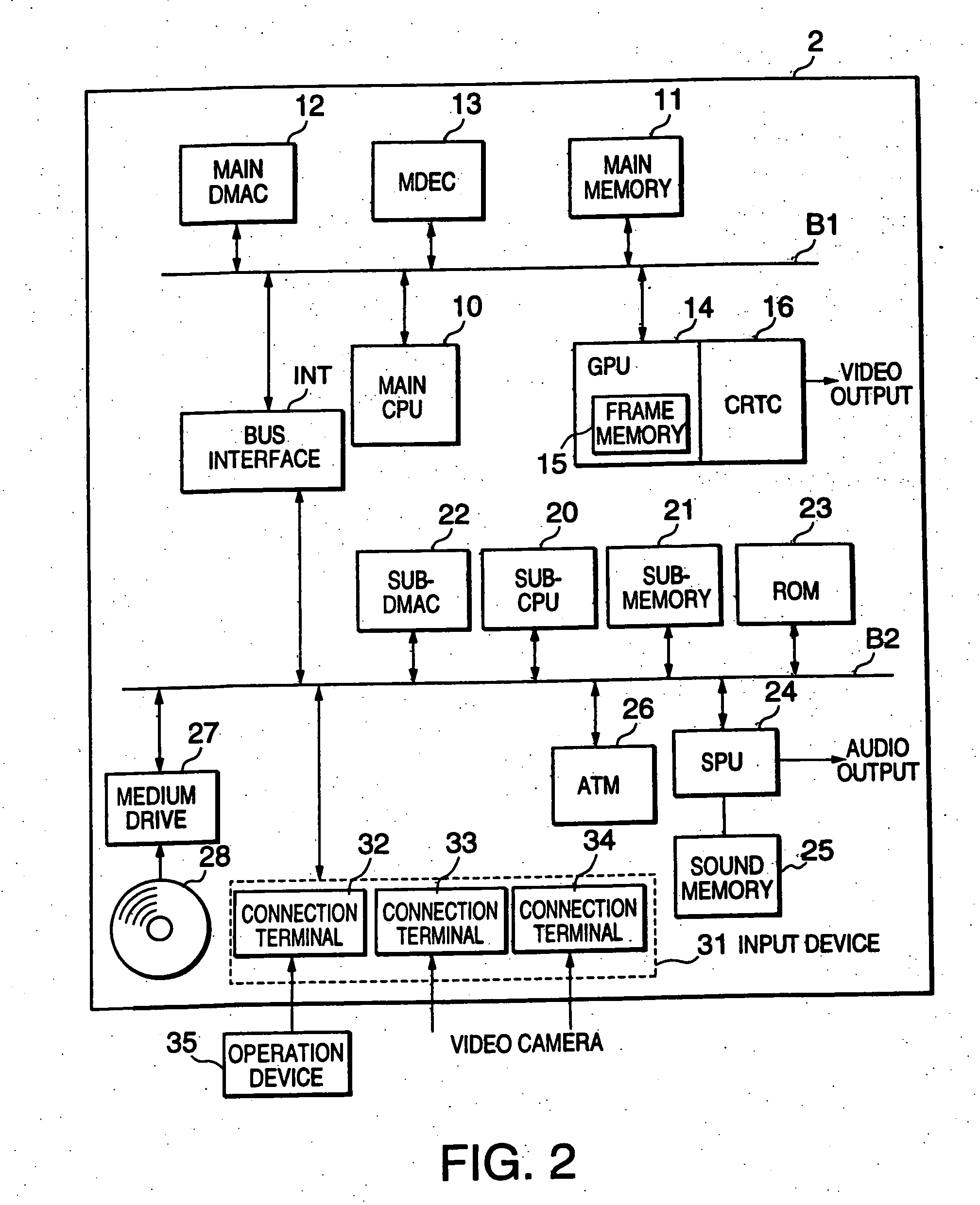
[0110] The image processing system according to this embodiment links an object image to a program that causes the main CPU 10 to execute an event to be subjected to image processing so that processing of the relevant event is executed according to the action of the operator within the mirrored moving image on the object image.

[0111] As an example of an object image to be superimposed on the mirrored moving image, this embodiment shows a case of using an image of a matchstick and an image of a flame expressing that the matchstick ignites and burns.

[0112] As a premise, the image of the matchstick, which is the object image, is linked beforehand to a program to display an ignition animation indicating that the matchstick has ignited on the display device 3. Then, when the operator in the mirrored moving image behaves as if he / she struck the image of the match within the combined image, the ignition animation is designed to appear in the ignition part of the image of the matchstick. ...

embodiment 3

[0133] Another embodiment will now be explained. As a premise, suppose the image processor 2 shows a combined image with a cursor (pointer) image, which is an example of an object image, superimposed on the mirrored moving image of the operator on the display device 3 as shown in FIG. 13(a). Also suppose a plurality of targets such as the hand, eyes, mouth of the operator are included in the mirrored moving image.

[0134] Here, a case will be explained whereby focusing on the movement of the operator's hand from the plurality of these targets, the cursor image is expressed in such a way as to follow this movement of the hand.

[0135] As shown in FIG. 13(a), the cursor image is an image like a face with an emphasis put on the eyes, which allows the eyes to be oriented toward the target. Furthermore, the cursor image moves following the movement of the target. That is, when the cursor image is distant from the target, the cursor image moves toward the target and when the cursor image ca...


PUM


Abstract

An image processor is provided which utilizes images taken by an imaging device, e.g., a digital camera, as an input interface to enter commands, etc. A memory is operable to store in real time a series of images of a location captured by the imaging device over time. A detector detects a target captured in the series of images and a quantitative value of a movement component of the target by detecting differences between features of the captured series of images between points in time. An image generator is operable to generate an object image, the object image following a movement of the detected target and including an image representing a trace of the movement. An image generator generates a combined image from the object image and an image from the captured series of images. An output is operable to output in real time a signal representing the combined image at the location captured in the series of images.

Description

CROSS-REFERENCE TO RELATED APPLICATIONS [0001] This application is a division of U.S. patent application Ser. No. 10 / 872,917 filed Jun. 21, 2004, which is a continuation of U.S. patent application Ser. No. 09 / 971,962 filed Oct. 5, 2001, the disclosures of both of these applications being hereby incorporated by reference herein. U.S. patent application Ser. No. 09 / 971,962 is based upon and claims the benefit of priority from the prior Japanese Patent Applications Nos. 2000-307574 filed Oct. 6, 2000, and 2001-295098 filed Sep. 26, 2001, the entire contents of these Japanese patent applications which are incorporated herein by reference.BACKGROUND OF THE INVENTION [0002] The present invention relates to an image processing technology for using an image taken by an image pickup apparatus such as a video camera as an interface for inputting commands, etc. [0003] A keyboard, mouse, controller, etc. are input devices often used for a computer, video game machine, etc. The operator inputs d...

Claims


Application Information

Patent Timeline
Patent Type & Authority Applications(United States)
IPC IPC(8): G09G5/00A63F13/213A63F13/52A63F13/55A63F13/655G06F3/00G06F3/01G06F3/033G06F3/048G06T1/00G06T7/00G06T7/254G06T13/00G06T13/80G09G5/377H04N7/18
CPCA63F2300/1087G06F3/011G06F3/0481G06T1/0007H04N7/183H04N21/42204H04N21/42222H04N21/4223H04N21/4312H04N21/44218H04N21/47G06F3/00
Inventor OHBA, AKIO
Owner SONY COMPUTER ENTERTAINMENT INC
Why Eureka
Try Eureka