
Image forming method and image forming apparatus

a technology of image forming and forming liquid, which is applied in the direction of measurement apparatus components, instruments, printing, etc., can solve the problems of affecting the quality of the image formed on the media, the movement of ink droplets deposited on the treatment liquid, and the marked decline of the quality of the image formed, so as to prevent the displacement of the landing position of the second liquid and cure the effect of the liquid

Inactive Publication Date: 2007-01-18
FUJIFILM CORP
View PDF0 Cites 79 Cited by
  • Summary
  • Abstract
  • Description
  • Claims
  • Application Information

AI Technical Summary

Benefits of technology

[0012] The present invention is conceived in view of the aforementioned circumstances, an object thereof being to provide an image forming method and an image forming apparatus, in order that a desirable image can be formed on a medium, by preventing the occurrence of image degradation due to landing interference on the medium, especially in the case of high-speed printing.

Problems solved by technology

Depending on the type of medium and the type of ink, when the ejected ink droplets permeate into the media, bleeding or spreading of the formed dots may occur, thus leading to a marked decline in the quality of the image formed.
However, according to a method whereby an ink droplet is ejected onto a treatment liquid deposited onto the media, the surface of the treatment liquid on the media onto which the ink droplets are ejected is not a completely flat surface, but rather the perimeter sections thereof in particular have a gradient, and hence the ink droplets deposited onto the treatment liquid may move due to this gradient.
In this way, the dots are not formed at the prescribed positions, due to the movement of the ink arising at the perimeter sections of the treatment liquid, and this affects the quality of the image formed on the media.
Furthermore, if an organic solvent having the high boiling point is used for the solvent of the treatment liquid, then the unreacted treatment liquid which is not incorporated into the polymer compound (monomer, oligomer, or the like) in the ink, does not cure and remains on the surface of the media.
Moreover, if the treatment liquid is deposited over a broader range than the ink droplet ejection range in such a manner that an ink droplet is not ejected onto the perimeter sections of the treatment liquid, then the amount of unreacted treatment liquid remaining on the surface of the media increases.
Japanese Patent Application Publications No. 10-287035, No. 2003-12971, and No. 2000-135781 do not disclose or suggest a concrete method for preventing landing interference in the case of high-speed printing.
If landing interference occurs on the recording medium, in the cases of ink droplets of the same color, a density non-uniformity may become visible, and the line quality may decline.
Furthermore, in the cases of inks of different colors, color bleeding may occur.

Method used


Image

  • Image forming method and image forming apparatus
  • Image forming method and image forming apparatus
  • Image forming method and image forming apparatus

Examples


Embodiment Construction

General Composition of Inkjet Recording Apparatus

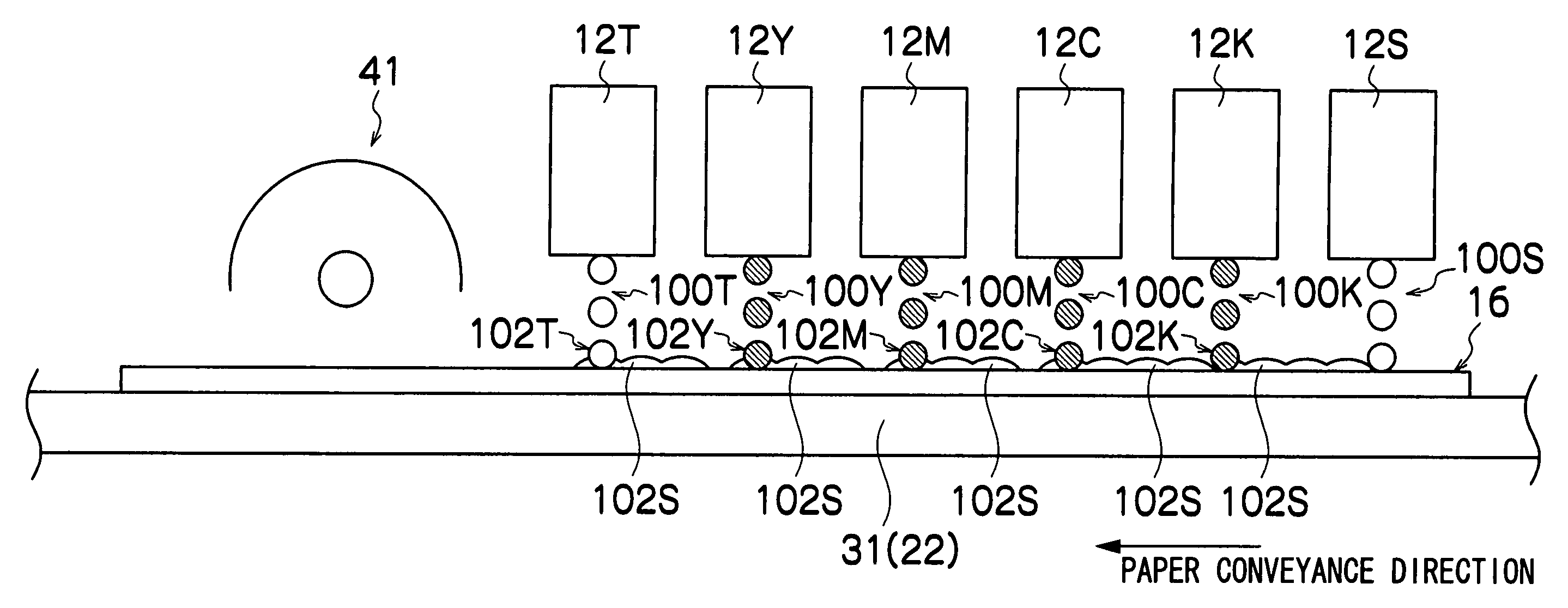
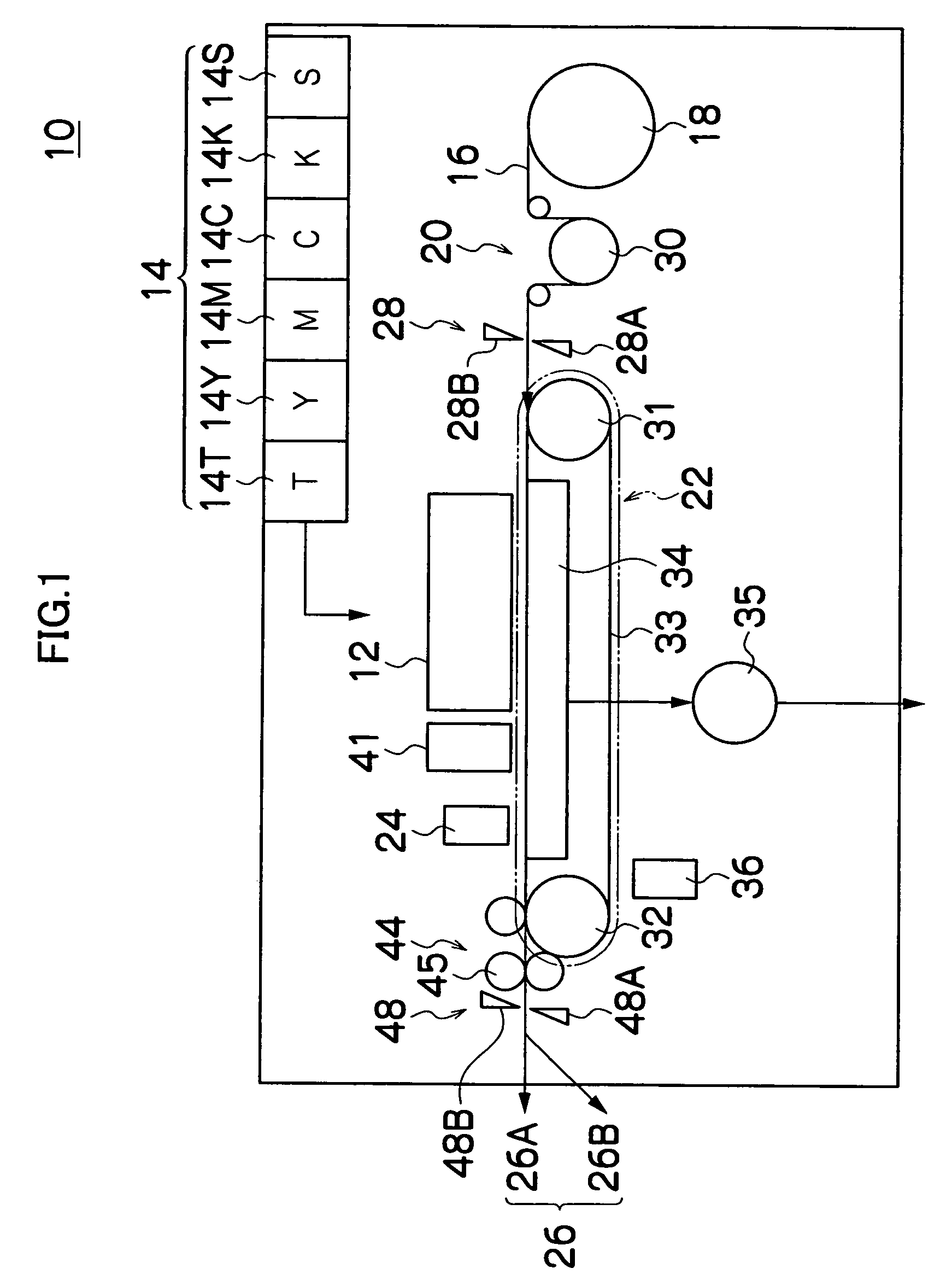
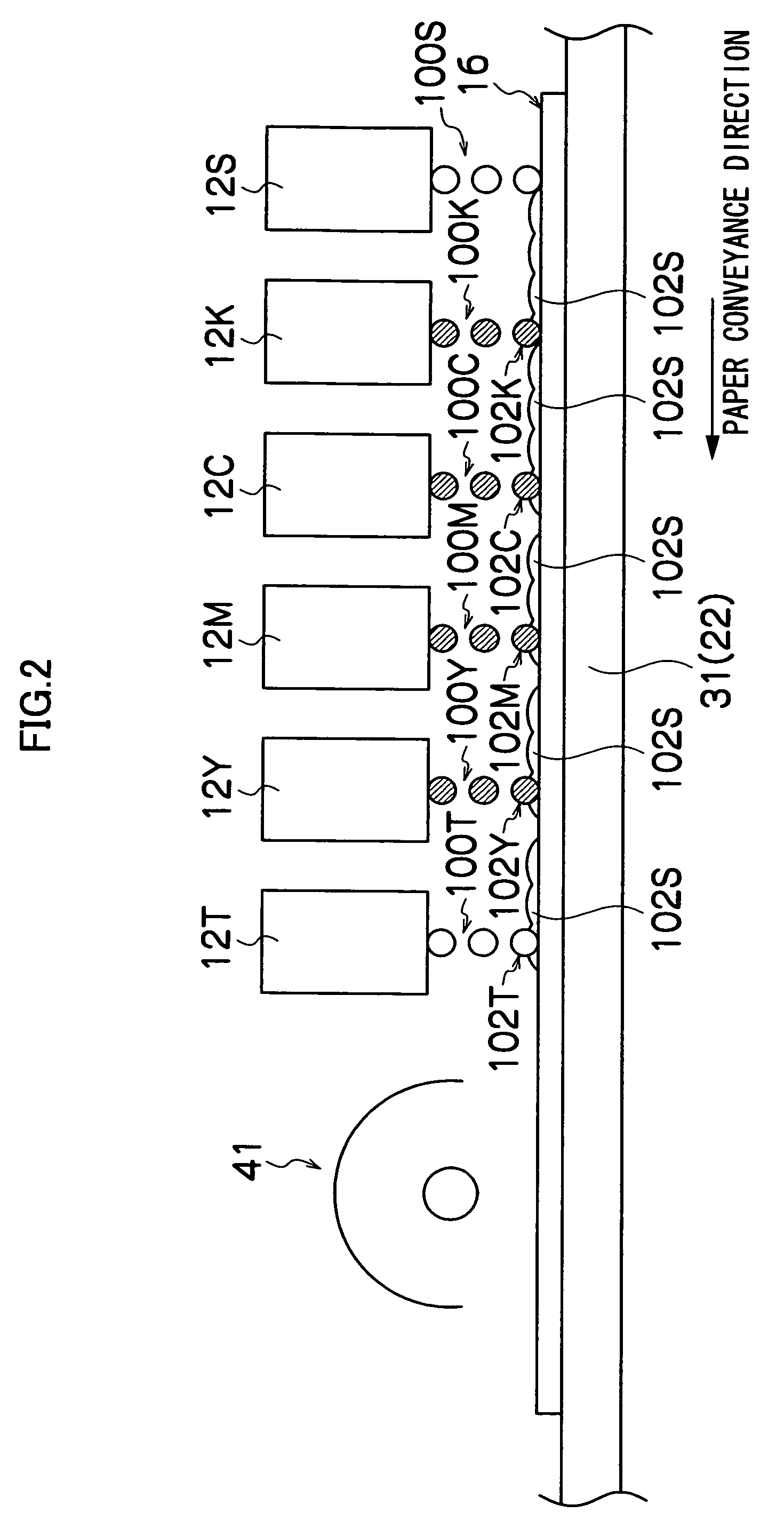
[0051]FIG. 1 is a diagram of the general composition of an inkjet recording apparatus relating to an embodiment of the present invention. As shown in FIG. 1, the inkjet recording apparatus 10 comprises: a print unit 12 having a plurality of inkjet heads (indicated by reference numerals 12K, 12C, 12M, and 12Y in FIG. 2) provided for ink colors of black (K), cyan (C), magenta (M), and yellow (Y), respectively, a treatment liquid head (indicated by reference numeral 12S in FIG. 2) corresponding to the treatment liquid (S) for avoiding landing interference between the inks of the respective colors, and a transparent ink head (indicated by reference numeral 12T in FIG. 2) corresponding to a transparent ink (T) which does not contain coloring material; an ink storing and loading unit 14 for storing inks to be supplied to the print heads; a paper supply unit 18 for supplying a recording medium (recording paper) 16; a decurling unit 20 remo...


PUM


Abstract

The image forming method includes the steps of: depositing a first liquid containing at least a dispersion inhibitor, a polymerization initiator, and a high-boiling-point organic solvent, onto an image forming region of a recording medium where an image is to be formed according to image data, and onto a peripheral region of the image forming region; ejecting a second liquid containing at least a radiation-curable polymer compound and a coloring material, onto the recording medium according to the image data after the first liquid is deposited onto the image forming region and the peripheral region of the image forming region; ejecting a third liquid containing at least a radiation-curable polymer compound, onto at least the peripheral region of the image forming region after the first liquid is deposited onto the image forming region and the peripheral region of the image forming region, the third liquid having a transparent color, the same color as the recording medium, or a similar color to the recording medium; and irradiating radiation onto the first liquid, the second liquid and the third liquid on the recording medium.

Description

BACKGROUND OF THE INVENTION [0001] 1. Field of the Invention [0002] The present invention relates to an image forming method and an image forming apparatus, and more particularly to image formation technology in an image forming apparatus for forming a desired image on a medium by reacting an image forming liquid such as ink with a treatment liquid and fixing the image forming liquid onto the medium. [0003] 2. Description of the Related Art [0004] In recent years, inkjet recording apparatuses have become common as image forming apparatuses which form images, such as photographic images, documents, or the like, on a medium. An inkjet recording apparatus forms a desired image on a medium by ejecting droplets of ink from nozzles, by driving ejection elements provided in the print head in accordance with data. [0005] Depending on the type of medium and the type of ink, when the ejected ink droplets permeate into the media, bleeding or spreading of the formed dots may occur, thus leading...

Claims


Application Information

Patent Timeline
IPC IPC(8): B41J2/01
CPCB41J2/2114B41J11/002B41J11/0015B41M7/0081B41J11/00214
Inventor KADOMATSU, TETSUZOKONNO, MASAAKIMAKUTA, TOSHIYUKI
Owner FUJIFILM CORP
Learn More