
Blending system

a technology of blending system and blending material, which is applied in the direction of mixers, cement mixing apparatuses, instruments, etc., can solve the problem of ill-suited sequence method

Inactive Publication Date: 2007-01-18
DIOSSE JEAN MICHEL +1
View PDF5 Cites 42 Cited by
  • Summary
  • Abstract
  • Description
  • Claims
  • Application Information

AI Technical Summary

Benefits of technology

[0010] The apparatus is preferably equipped with sensors to measure the effective flow rate of a selected element and a cont...

Problems solved by technology

This sequential method is ill-suited if the individual volume (or mass) fractions of the different components of the mixture are dramatically different.

Method used


Image

  • Blending system
  • Blending system
  • Blending system

Examples


Embodiment Construction

[0021] The same references will be used to reference the same elements in the Figures throughout the description.

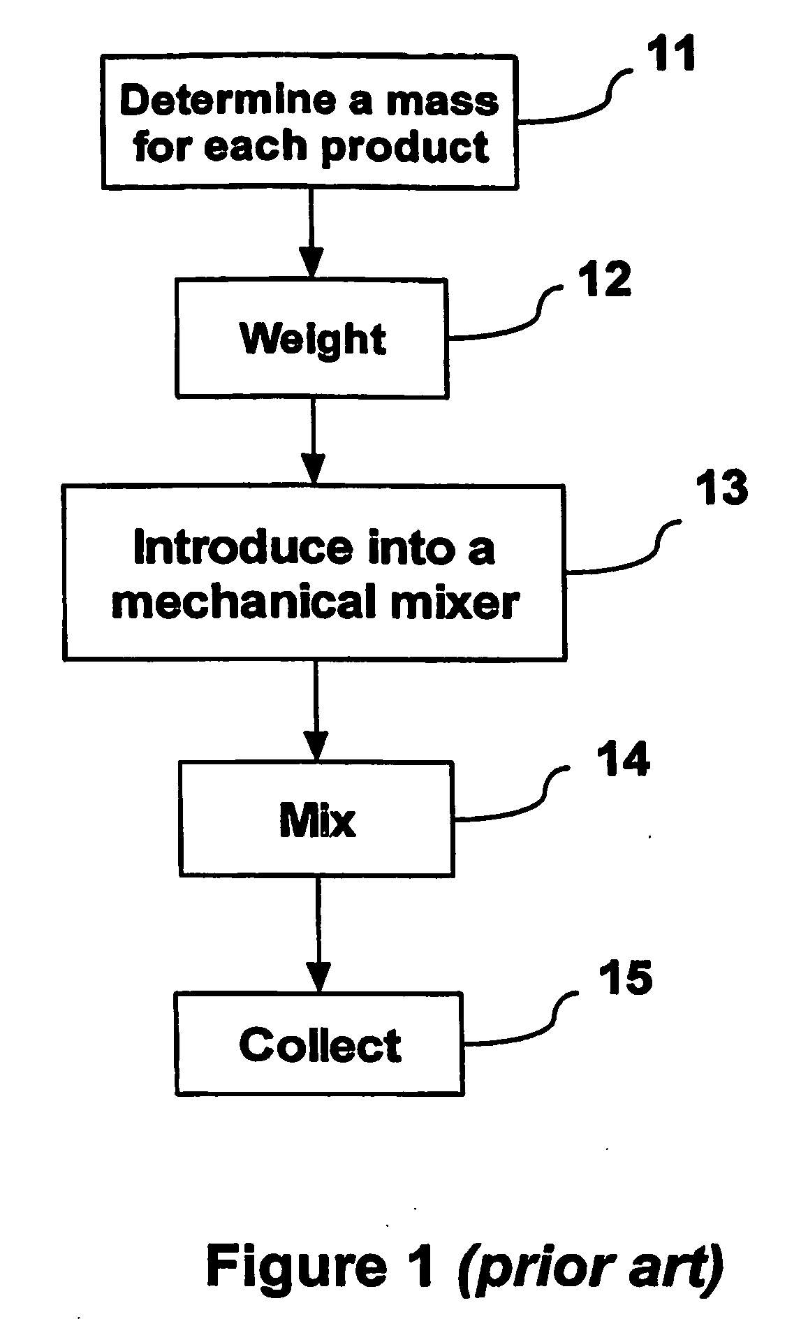
[0022] The cement blending known from the prior art is a sequential process, during which each product is weighed before being poured into the mixing device. When such cement blending is repeated to produce several batches, the batches may not be perfectly identical. For this reason, a production quality for cement blended in the sequential process may vary from one batch to another.

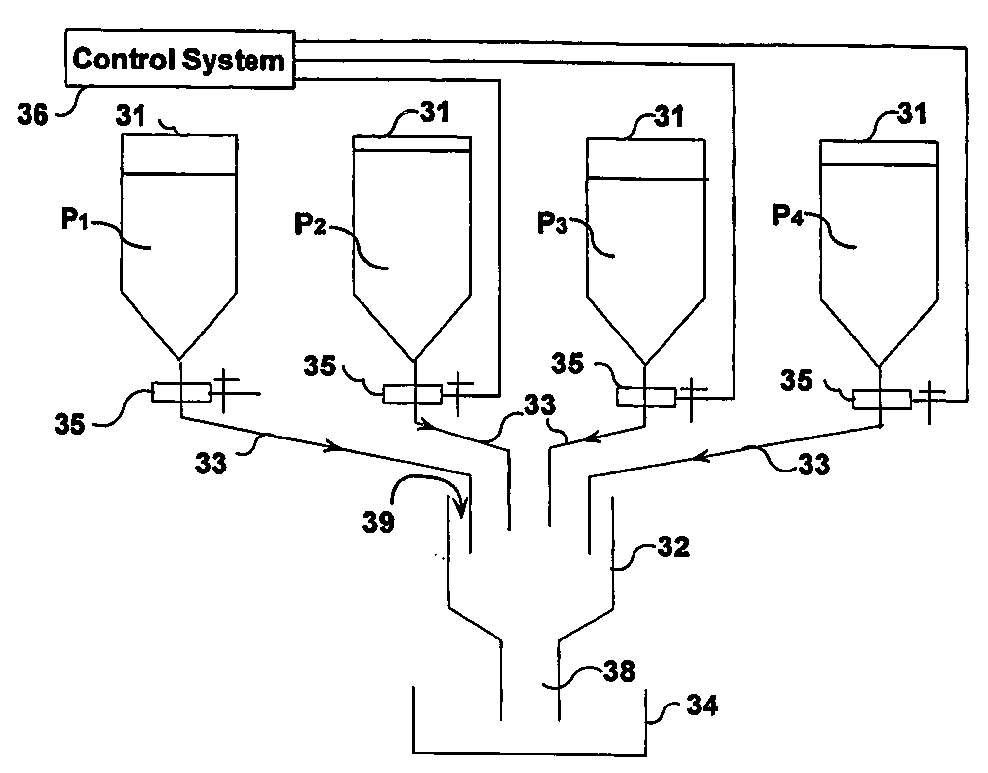
[0023] The present invention allows obtaining a substantially constant production quality when blending cement. The present invention may produce identical batches, or a continuous flow of blend for any quantity of cement mixture.

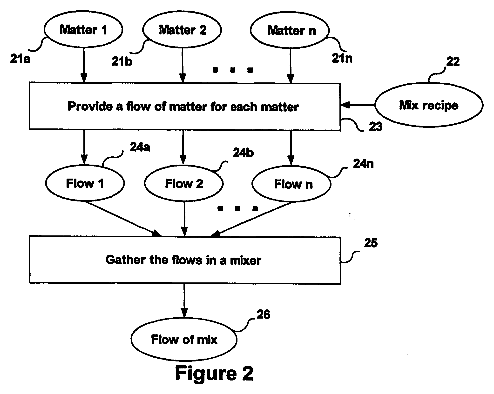
[0024]FIG. 2 provides a flowchart illustrating an example of the present invention. A first flow of cement 21a is provided. For each other material (21b, . . . 21n), for example low density paniculate materials such as micro-spheres, fine particulate materials such...


PUM

PropertyMeasurementUnit
Angleaaaaaaaaaa
Flow rateaaaaaaaaaa
Ratioaaaaaaaaaa

Abstract

A method, for obtaining a mix of a plurality of matters in a fluid state comprises providing for a first matter of the plurality of matters a first flow of matter. For each matter of the plurality of matters distinct from the first matter, a flow of matter is provided at a determined flow rate. The method further comprises gathering each flow of matter at an inlet of a mixer, the mixer continuously producing at an outlet a substantially homogeneous flow of matter corresponding to the mix.

Description

FIELD OF THE INVENTION [0001] The present invention relates to a system for blending materials. In particular it relates to a system for blending materials that go to make up a cement slurry such as may be used in a well cementing operation. BACKGROUND ART [0002] Obtaining fluid mixtures often involves blending a plurality of materials according to a predetermined mixture recipe. The materials may, for example, be liquids, gels, or solids in particulate and / or powder form. The mixture recipe typically indicates the ratio of each product. Hence, to obtain any final quantity of the mixture it is necessary to determine for each product a respective required quantity. [0003] The blending is often a sequential process. At first the required quantity for each of the materials is measured, e.g., by weight or by volume. The products are then poured into a mixing device, either one after the other or together, where they are mixed. This may for example be achieved mechanically, for example b...

Claims


Application Information

Patent Timeline
IPC IPC(8): B28C7/04B01F15/04B01F5/24B01F15/00G05D11/13
CPCB01F5/241B01F15/00123G05D11/131B01F15/00344B01F15/0412B01F15/00136B01F25/82B01F35/2111B01F35/2211B01F35/83B01F35/21
Inventor DIOSSE, JEAN-MICHELVERMET, FRANCK
Owner DIOSSE JEAN MICHEL
Features
  • Generate Ideas
  • Intellectual Property
  • Life Sciences
  • Materials
  • Tech Scout
  • Unparalleled Data Quality
  • Higher Quality Content
  • 60% Fewer Hallucinations
Learn More