Optimized RFID/NFC BER testing

a technology of rfid/nfc ber and testing mode, applied in the field of wireless communication, can solve the problems of wasting resources applied to provide information, cellular network may not be appropriate for all data applications, and may not be suitable for all data applications

Inactive Publication Date: 2007-01-18
NOKIA TECHNOLOGLES OY
View PDF3 Cites 55 Cited by
  • Summary
  • Abstract
  • Description
  • Claims
  • Application Information

AI Technical Summary

Benefits of technology

[0016] In this way, the overall test information may segregate packet errors occurring on the transmission phase (initiating device to the secondary device) from the reception phase (secondary device back to the initiating device). The capturing of this precise error information allows a user to pinpoint where errors in transmission occur, and may indicate a known problem, and accordingly, a possible solution.

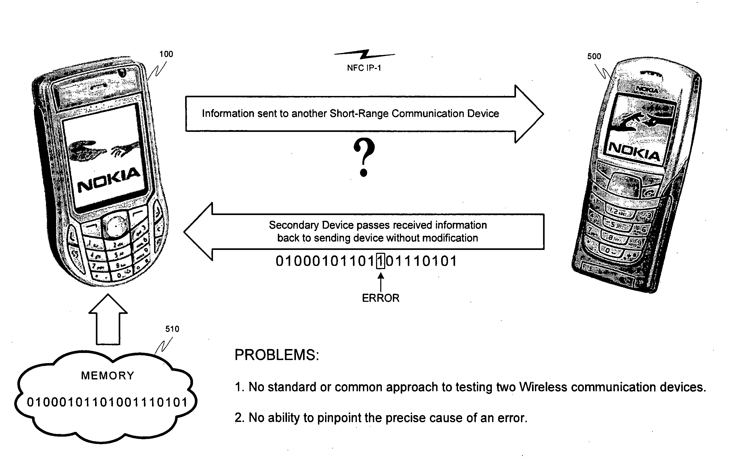
Problems solved by technology

While cellular networks like GSM provide a global means for transmitting and receiving data, due to cost, traffic and legislative concerns, a cellular network may not be appropriate for all data applications.
While these beneficial characteristics make NFC IP-1 communications ideal for many applications, the actual usefulness of radio frequency communication methods may be limited by the reliability of the wireless connection.
Otherwise, the resources applied to provide this information are wasted.
The current testing methods, while effective to evaluate overall connection quality, are not Well equipped to help a user pinpoint the source of an error.
There is also no standardization for these tests, requiring a custom set-up according to the circumstances of each particular test.
Finally, special equipment and software (e.g., a test program used to send test packets) may not be readily available to all users who desire to debug a device (e.g., a field technician).
Currently, providing these test resources for all WCD users may be prohibitive due to the additional resource overhead required in the device.
This additional space for equipment and / or software may require substantial redesign and cost escalation for the device.

Method used


Image

  • Optimized RFID/NFC BER testing
  • Optimized RFID/NFC BER testing
  • Optimized RFID/NFC BER testing

Examples


Embodiment Construction

[0029] While the invention has been described in preferred embodiments, various changes can be made therein without departing from the spirit and scope of the invention, as described in the appended claims.

I. Wireless Communication Device

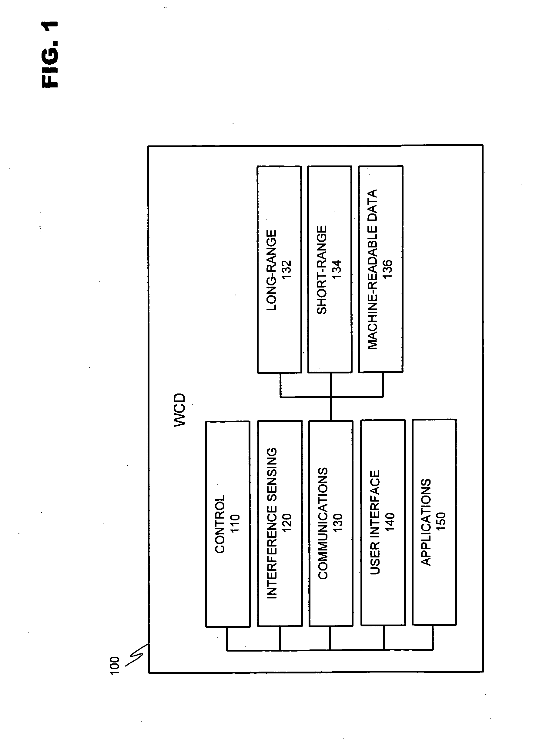
[0030]FIG. 1 discloses an exemplary modular layout for a wireless communication device usable with the instant invention. WCD 100 is broken down into modules representing the functional aspects of the device. These functions may be performed by the various combinations of software and / or hardware components discussed below.

[0031] Control module 110 regulates the operation of the device. Inputs may be received from various other modules included within WCD 100. For example, interference sensing module 120 may use various techniques known in the art to sense sources of environmental interference within the effective transmission range of the wireless communication device. Control module 110 interprets these data inputs and in response may issue co...


PUM


Abstract

A system and method for testing communication performance between two wireless communication devices. A value table is used to determine a test string in both the unit under test and another wireless device. An initiating device transmits data to the secondary device, which may check the incoming data for errors against an “expected” data string. The secondary device may then correct the incoming data (if necessary) and transmit it back to the initiating device. The initiating device may check this data and combine it with data from the secondary device in order to determine an overall bit error rate (BER) and / or packet error rate (PER).

Description

BACKGROUND OF INVENTION [0001] 1. Field of Invention [0002] The present invention relates to wireless communication. More particularly, the invention is related to an improved system for bit error rate (BER) and packet error rate (PER) testing of wireless short-range communications between two devices. [0003] 2. Description of Prior Art [0004] A wireless communication device (WCD) may communicate over a multitude of networks. Cellular networks facilitate WCD communications over large geographic areas. For example, the Global System for Mobile Telecommunications (GSM) is a widely employed cellular network that communicates in the 900 MHZ-1.8 GHZ band in Europe and at 1.9 GHZ in the United States. This system provides a multitude of features including audio (voice), video and textual data communication. For example, the transmission of textual data may be achieved via the Short Messaging Service (SMS). SMS allows a WCD to transmit and receive text messages of up to 160 characters. It ...

Claims


Application Information

Patent Timeline
Patent Type & Authority Applications(United States)
IPC IPC(8): H04B17/00H04L43/50H04W24/00H04W28/04H04W84/10
CPCH04L1/243H04L12/2697H04L43/50H04W28/04H04L1/203H04B17/0085H04B5/0062H04B5/0031H04W24/08H04W84/10H04W24/06
Inventor ROWSE, GRAHAMPENDLEBURY, JOE
Owner NOKIA TECHNOLOGLES OY
Why Eureka
Try Eureka