Method of and system for splitting compound objects in multi-energy computed tomography images

a computed tomography and compound object technology, applied in the field of methods, can solve the problems of difficult detection of plastic explosives, difficult formation of plastic explosive geometric shapes, and difficulty in discriminating plastic explosives, and achieve the effect of improving discrimination accuracy

Inactive Publication Date: 2007-01-18
ANLOGIC CORP (US)
View PDF53 Cites 41 Cited by
  • Summary
  • Abstract
  • Description
  • Claims
  • Application Information

AI Technical Summary

Benefits of technology

[0078] In accordance with one aspect of the present disclosure, compound object detection is performed on each segmented object. The compound object detection computes and uses the standard deviation of objects' density and atomic number measurements for detection. When a compound object is detected, compound object splitting is performed to segment the compound object into different component objects to improve the discrimination accuracy.

Problems solved by technology

Plastic explosives, however, present a particular challenge to baggage scanning systems.
Due to their moldable nature, plastic explosives may be formed into geometric shapes that are difficult to detect.
The detection of plastic explosives may be difficult because it may be difficult to see the explosive material in the image, particularly when the material is disposed so that the thin sheet is parallel to the direction of the X-ray beam as the sheet passes through the system.
Accordingly, a great deal of effort has been made to design a better baggage scanner.
To meet high baggage throughput rates, a conventional CT baggage scanner such as the InVision Machine can only afford to generate a few CT images per bag.
Clearly, one cannot scan the entire bag within the time allotted for a reasonably fast throughput.
Generating only a few CT images per baggage items leaves most of the item unscanned and therefore does not provide scanning adequate to identify all potential threat objects in the bag, such as sheets of explosive material.
A significant drawback to the Eberhard et al. system is that it may miss thin objects such as sheet explosives that are not viewed edge-on and which cover a large area of the bag.
The images from the post-reconstruction analysis usually do not yield accurate estimates of the material's effective atomic number, and suffer low SNR (Signal to Noise Ratio) and many artifacts as well.
The isotransmission line method requires a large amount of calibration data.
In such a situation, the linear equations are not valid and the method causes large approximation errors.
CT scanners are not perfect imaging devices, and there is a partial volume effect on density images; that is, the density value resented in the CT image is much lower than the physical density of a thin object, such as a steel bowl and a thermos bottle.
The unsuccessful segmentation result degrades the performance for object detection.

Method used


Image

  • Method of and system for splitting compound objects in multi-energy computed tomography images
  • Method of and system for splitting compound objects in multi-energy computed tomography images
  • Method of and system for splitting compound objects in multi-energy computed tomography images

Examples


Embodiment Construction

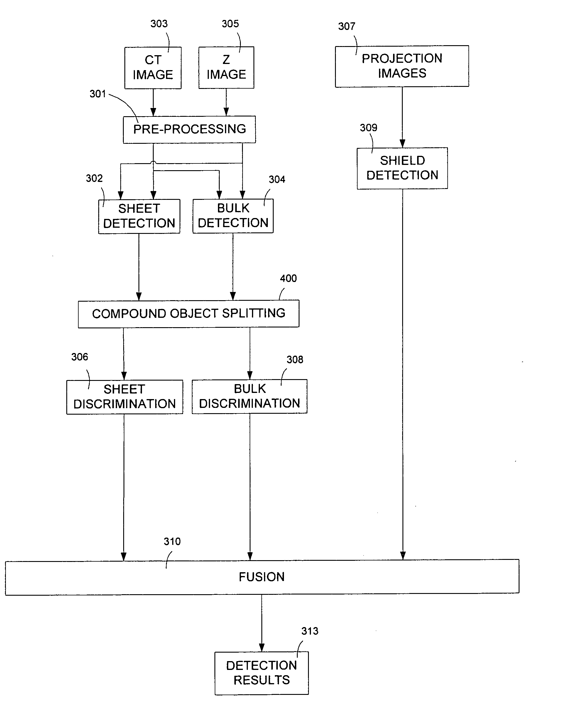
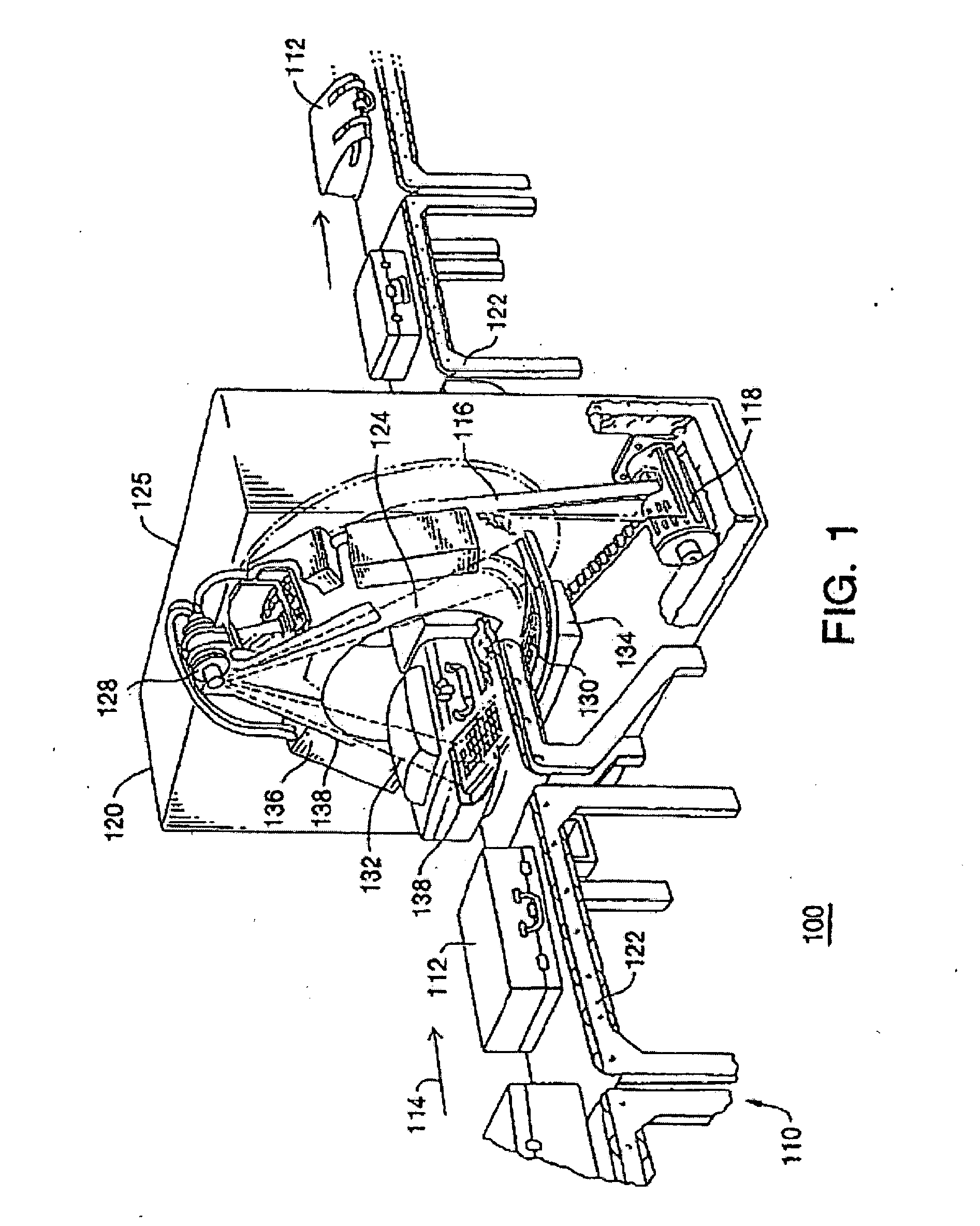
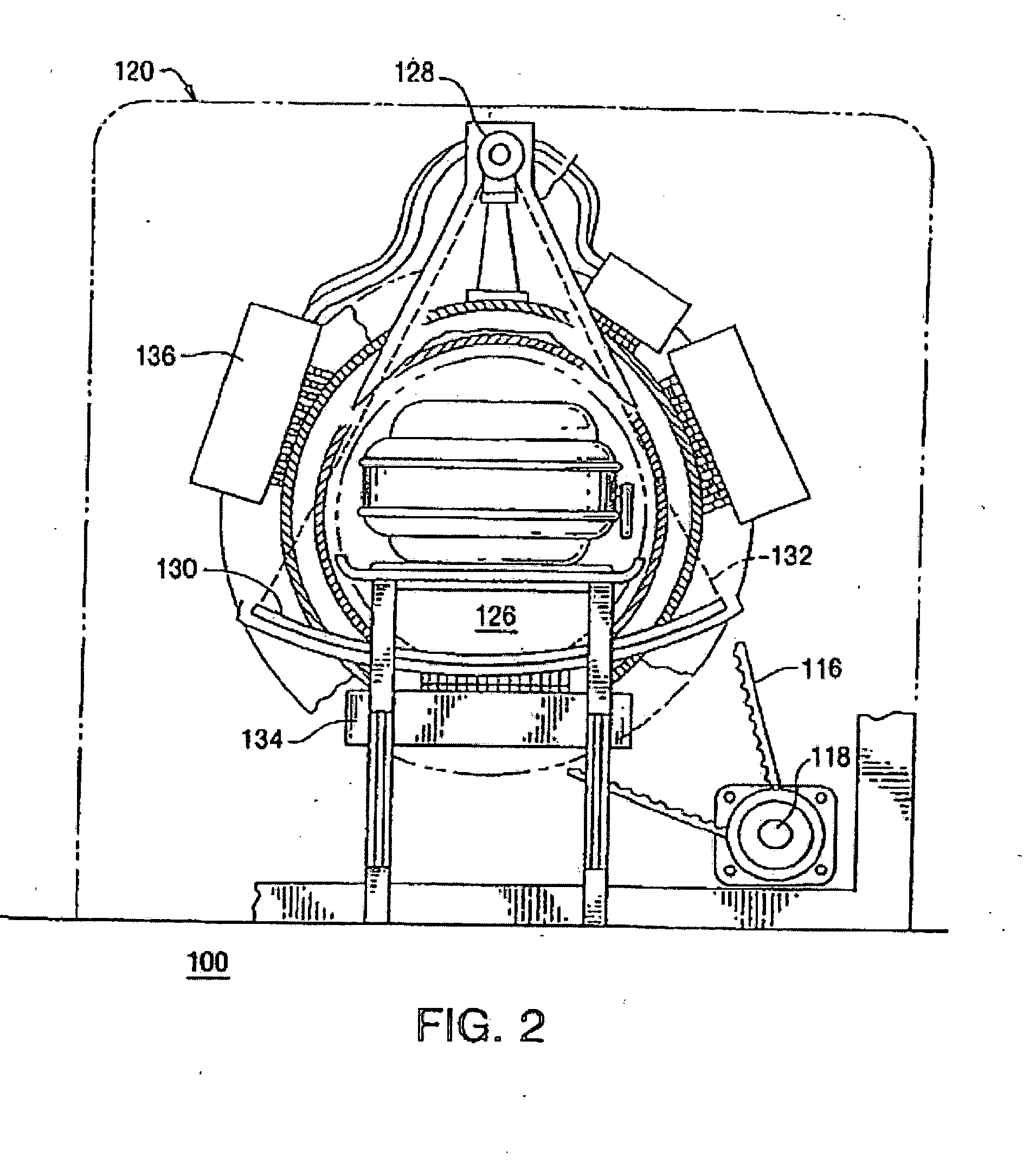
[0097] The present disclosure provides a system and a method which detect, identify and / or classify objects in multi-energy CT data including a CT image, which approximates the density measurements of the scanned objects, and a Z (effective atomic number) image, which approximates the atomic number measurements of scanned objects. The disclosure can therefore be implemented in a CT baggage scanning system. The objects identified by the disclosure can be objects known to pose threats to persons at an airport or on board an aircraft. These objects can include explosive objects and materials.

[0098] The generation of the CT image and Z image from a dual energy CT scanner uses methods described in the assignee's “Method of and system for adaptive scatter correction in multi-energy computed tomography” by Zhengrong Ying, et al. U.S. application Ser. No. 10,853,942, filed on May 26, 2004 (Attorney's Docket No. 56230-608 (ANA-255)); incorporated herein by reference; “Method of and system f...


PUM


Abstract

A method of and a system for splitting a compound object using multi-energy CT data including a density and an atomic number measurements are provided. The method comprises: compound object detection; computing a two-dimensional DZ distribution of a compound object; identifying clusters within the DZ distribution; assigning a component label to each object voxel based on the DZ distribution clusters; and post-processing the set of voxels identified as belonging to each component.

Description

RELATED APPLICATIONS [0001] This patent application and / or patents are related to the following co-pending U.S. applications and / or issued U.S. patents, of the assignee as the present application, the contents of which are incorporated herein in their entirety by reference: [0002]“Dual energy power supply,” invented by Bernard M. Gordon, et al., U.S. Pat. No. 5,661,771, issued on Aug. 26, 1997; [0003]“Nutating Slice CT Image Reconstruction Apparatus and Method,” invented by Gregory L. Larson, et al., U.S. application Ser. No. 08 / 831,558, filed on Apr. 9, 1997, now U.S. Pat. No. 5,802,134, issued on Sep. 1, 1998; [0004]“Computed Tomography Scanner Drive System and Bearing,” invented by Andrew P. Tybinkowski, et al., U.S. application Ser. No. 08 / 948,930, filed on Oct. 10, 1997, now U.S. Pat. No. 5,982,844, issued on Nov. 9, 1999; [0005]“Air Calibration Scan for Computed Tomography Scanner with Obstructing Objects,” invented by David A. Schafer, et al., U.S. application Ser. No. 08 / 948...

Claims


Application Information

Patent Timeline
Patent Type & Authority Applications(United States)
IPC IPC(8): G06K9/00G06K9/46
CPCG01T1/2985G01V5/0041G06K9/6219G06K9/00771G01V5/005G06V20/52G06V10/7625G06F18/231
Inventor SIMANOVSKY, SERGEYYING, ZHENGRONGCRAWFORD, CARL R.
Owner ANLOGIC CORP (US)
Why Eureka
Try Eureka